background image

ENGLISH 


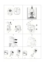
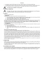
10.1 Cleaning the suction grid 

(Fig.7) 


Switch off the electric power supply to the pump

.


Drain the pump.


Unscrew the retaining screws on the filter (

b

).


Remove the suction grid 

 (

c

)


Clean and reassemble the suction grid

.


10.2 Cleaning the impeller   

(Fig.8) 


Switch off the electric power supply to the pump


Drain the pump. 


Unscrew the retaining screws on the filter (

b

). 


Remove the suction grid (

c


Wash the pump with clean water to remove possible 

impurities between the motor and the pump jacket. 
(

d

). 


Clean the impeller

 (

d

). 


Check that the impeller can turn freely


Assemble the parts, proceeding in inverse order to 

disassembly. 

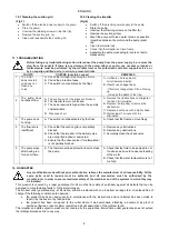
11.  TROUBLESHOOTING  


Before taking any troubleshooting action, disconnect the pump from the power supply (i.e. remove the 
plug from the socket). If there is any damage to the power cable or pump, any necessary repairs or 
replacements must be performed by the manufacturer or his authorized customer support service, or 
by an equally-qualified party, in order to prevent all risks.


FAULTS


CHECKS (possible causes)


REMEDIES


The motor 
does not start 
and does not 
make any 
noise.


A. 

Check that voltage is reaching the motor

.


B.  Check the protection fuses. 
C.  The switch is not activated by the float. 

A. Verificare che la spina sia 

correttamente inserita 

B. If burnt out, change them. 

-


If burnt out, change them. Place it facing 

up. 
- Increase the depth of the trap. 


The pump does 
not deliver flow 

A. 

The suction grid or the pipes are blocked.


B.  The impeller is worn or blocked. 
C.  The head required is higher than the pump’s 

characteristics. 

D. 

Presence of air


A. 

Remove the obstructions or straighten 
the hose if it is twisted.


B. 

Replace the impeller or remove the 
obstruction.


C. Replace it with one with a higher head.  

D. 

Wait at least 1 minute until it is 
eliminated


The pump does 
not stop. 

A.  The switch is not deactivated by the float 

A. Check that the float can move freely. 

The flow rate is 
insufficient 

A.  Check that the suction grid is not partially 

blocked 

B.  Check that the impeller or the delivery pipe 

are not partly blocked or encrusted. 

C.  Ensure that the check valve (if contemplated) 

is not partially blocked 

A. Remove any obstructions. 
B. Remove any obstructions. 
C. Accurately clean the check valve 

The pump stops 
after having run 
for a short time. 
 

A.  The thermal overload protection device stops 

the pump. 


A. Check that the fluid to be pumped is not 

too dense as it would cause overheating 
of the motor. 

B. Check that the water temperature is not 

too high. 


12.  GUARANTEE 


Any modification made without prior authorisation relieves the manufacturer of all responsibility. All the 
spare parts used in repairs must be authentic and all accessories must be authorised by the 
manufacturer, in order to ensure maximum safety of the machines and of the systems in which they may 
be installed. 

This product is covered by a legal guarantee (for 24 months from date of purchase) against all defects that can be 
assigned to manufacturing faults or to the material used.  
The product under guarantee may, at discretion, either be replaced with one in perfect working order or replaced free of 
charge if the following conditions are observed: 


the product has been used correctly in compliance with the instructions and not attempt has been made to 

repair it by the buyer or by third parties. 


the product has been consigned to the outlet where it was purchased, attaching a document as proof of 

purchase (invoice or cash register receipt) and a brief description of the problem found. 

The impeller and parts subject to wear are not covered by the guarantee. Intervention under guarantee does not extend 
the initial guarantee period in any way.  

Summary of Contents for P1 330W

Page 1: ...INSTRUCTIONS FOR INSTALLATION AND MAINTENANCE GB INSTRUCTIONS POUR L INSTALLATION ET LA MAINTENANCE FR INSTRUCCIONES DE INSTALACI N Y MANTENIMIENTO ES INSTRU ES PARA A INSTALA AO PT...

Page 2: ...ENGLISH Pag 1 FRAN AIS Page 5 ESPA OL P g 9 PORTUGU S Pag 13...

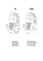
Page 3: ...A NA Automatic Not Automatic Automatique Pas Automatique Autom tico No autom tico Autom tico N o autom tico...

Page 4: ...1 2 3 4 5 6 7 8...

Page 5: ...tc Thanks to their compact and handy shape they are also used for particular applications as portable pumps for emergency situations such as for drawing water from tanks or rivers draining swimming po...

Page 6: ...ging indicates the total weight of the pump and its dimensions 5 WARNINGS The pumps must never be carried lifted or allowed to operate suspended from the power cable use the handle provided The pump m...

Page 7: ...he minimum starting and stopping height see the Technical Data chapter The cable length must on one hand allow the float switch to move freely and on the other prevent it resting on the bottom The por...

Page 8: ...D Wait at least 1 minute until it is eliminated 3 The pump does not stop A The switch is not deactivated by the float A Check that the float can move freely 4 The flow rate is insufficient A Check tha...

Page 9: ...r forme compacte et maniable elles peuvent tre utilis es galement comme pompes portatives pour les cas d urgence comme le puisage d eau dans des r servoirs ou des rivi res le vidage de piscines ou de...

Page 10: ...produits des chocs et collisions 4 3 Poids et dimensions La plaque adh sive plac e sur l emballage indique le poids total de l lectropompe et ses dimensions 5 AVERTISSEMENTS Les pompes ne doivent jama...

Page 11: ...uteur de d marrage arr t pour conna tre la hauteur d activation et de d sactivation minimale consulter le chapitre Donn es techniques La longueur du c ble doit d un c t permettre l interrupteur flotta...

Page 12: ...E L interrupteur n est pas d sactiv par le flotteur A V rifier que le flotteur bouge librement 4 Le d bit est insuffisant A V rifier que la cr pine d aspiration n est pas partiellement bouch e B V ri...

Page 13: ...canalones etc Gracias a su forma compacta y manejable son adecuadas para empleos especiales como bombas port tiles para casos de emergencia como por ejemplo extraer agua de dep sitos o r os vaciar pi...

Page 14: ...productos a golpes y choques in tiles 4 3 Peso y medidas En la placa adhesiva aplicada en el embalaje se indican el peso total de la electrobomba y sus medidas 5 ADVERTENCIAS Las bombas nunca se deben...

Page 15: ...y seguir funcionando hasta que se alcance el nivel de OFF Regulaci n de la altura de arranque parada Para conocer la altura m nima de activaci n y desactivaci n consultar el cap tulo Datos t cnicos La...

Page 16: ...s 1 minuto hasta que se purgue el aire 3 La bomba no se detiene A El flotador no desactiva el interruptor A Comprobar que el flotador se mueva libremente 4 El caudal es insuficiente A Comprobar que la...

Page 17: ...forma compacta e mane vel tamb m pode ser utilizada como bomba port til para emerg ncias como aspira o de gua de reservat rios ou rios esvaziamento de piscinas e chafarizes ou de escava es e passagens...

Page 18: ...eso e dimens es Na plaqueta adesiva da embalagem est indicado o peso total da eletrobomba e as suas dimens es 5 AVISOS As bombas nunca devem ser transportadas levantadas ou acionadas se suspensas pelo...

Page 19: ...ura de arranque paragem Para conhecer a altura de arranque e paragem m nima consultar o cap tulo Dados t cnicos O comprimento do cabo deve permitir que o interruptor de boia movimente se livremente e...

Page 20: ...la por uma de altura manom trica superior D Aguardar pelo menos 1 minuto at ser eliminado 3 A bomba n o para A O interruptor n o desativado pela boia A Verificar se a boia movimenta se livremente 4 O...

Page 21: ...02 18 cod 60187264...

Reviews: