ENGLISH
3
Pay attention to ensure that the float is free to move, leave at least 5 cm (2”) from the wall of the trap.
The dimensions of the trap must always be in relation to the quantity of water arriving and to the flow of the pump, so
as not to subject the motor to excessive starts/hour; it is strongly recommended not to exceed 20 starts/hour.
The pump must be installed in vertical position!
7. ELECTRICAL CONNECTION
The length of the power cable on the pump limits the maximum depth of immersion in use of the pump.
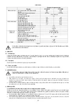
Follow the indications on the technical data plate and in this manual, table 2.
8. START-UP
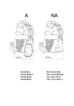
There are two operating modes:
MANUAL (A)
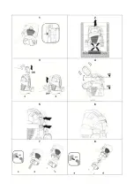
Although they have a float, the pumps can be used in manual mode Fig.3
1)
Fix the float switch so that it remains vertical above the pump (with the cable below) (a). As long as the float
switch remains raised, the pump keeps operating irrespective of the water level.
2) Insert the plug of the power cable in a 115 – 120 V power socket.
3) The pump will start up; ensure that it is immerse in the liquid to be pumped.
Pay attention because the pump will not switch off automatically once it reaches the minimum level; it must be switched
off manually by the user, either by taking the power out of the socket or by lowering the float (automatic operation).
The maximum suction level is reached only during manual operation because, in automatic operating condition, the
automatic float switch stops the pump before it reaches that level.
AUTOMATIC (B)
The models with a float switch are started automatically when the water level rises and will switch off when the required
minimum level is reached (Fig.4).
1) Leave the float free to move.
2) Insert the plug of the power cable in a 115 – 120 V power socket.
3) When the float reaches the ON level the pump will start and will continue operating until it reaches the OFF
level.
Regulating the starting/stopping height:
(To know the minimum starting and stopping height, see the Technical Data chapter.)
The cable length must on one hand allow the float switch to move freely and, on the other, prevent it resting on the
bottom. The portion of cable between the float switch and the cable stay notch must not be less than 10 cm (3.94”) long
The shorter the portion of cable between the float switch and the cable stay notch, the lower will be the starting height
and the higher the stopping height. The fixing point can be changed, for example on the lower clip, with the same length,
this will give a lower stopping and starting level (Fig.5). The pump is supplied with a clamp (Fig. 6) that fixes the float
cable and prevents it sliding in the clip; if you decide to lengthen or shorten the free float cable, shift the corresponding
clamp if it cannot be replaced. The single-phase motors are equipped with built-in thermal overload protection and can
be connected directly to the mains. NB: if the motor is overloaded it stops automatically. Once it has cooled it starts again
automatically without requiring any manual intervention.
A filter is designed in such a way as to regulate the free passage from 30 mm (1.18”) to 5 mm (0.20”); if it is used with
clear water, just turn it and lower it.
9. PRECAUTIONS
RISK OF FROST: when the pump remains inactive at a temperature lower than 32 F, it is necessary to ensure that there
is no water residue which could freeze, causing cracks in the plastic parts.
If the pump has been used with substances that tend to form a deposit, or with water containing chlorine, rinse it after
use with a powerful jet of water in order to avoid the formation of deposits or encrustations which would reduce the
characteristics of the pump.
10. MAINTENANCE AND CLEANING
In normal operation the pump does not require any type of maintenance. In any case, all repair and maintenance work
must be carried out only after having disconnected the pump from the supply mains. When restarting the pump, ensure
that the suction filter is always fitted so as not to create the risk or possibility of accidental contact with moving parts.


