background image

Pro Pump Controller (ProCon-100) 


Rev3.6 

2023/07/17 

29/70 

Copyright 

©

 2023 by TAEHA CORP. All Rights Reserved


5.3.2


  Shot Speed Setting 


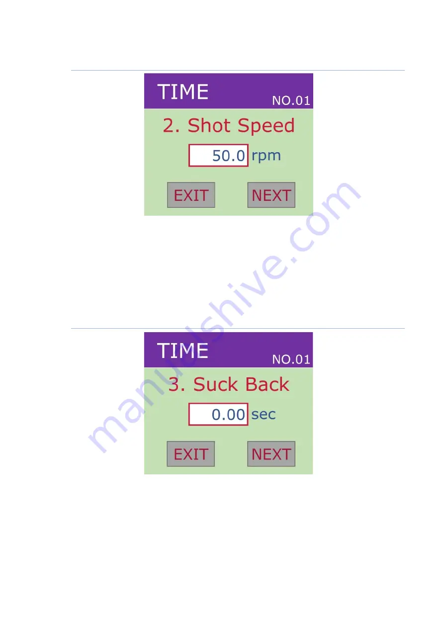
Figure 11. Shot Speed Setting Screen 


-


Adjust the speed of the pump.(0~9999.99sec) 

-


By selecting the up/down key or data box, you can set the value through the key pad screen. 

-


If you want to go to the next setting menu, click 

‘Next’ button

-


If you want to go to the main screen, click 

‘Exit’ button


5.3.3


  Suck Back Time Setting 


Figure 12. Suck-back Time Setting Screen 


-


Set the suction time for the solution. (0~9999.99sec) 

-


By selecting the up/down key or data box, you can set the value through the keypad screen. 

-


I

f you want to go to the next setting menu, click ‘Next’ button

-


If you want to go to the main screen, cl

ick ‘Next’ button

Summary of Contents for PROCON-100

Page 1: ...Pro Pump Controller PROCON 100 Operation Manual...

Page 2: ...ance and Specifications of ProCon 100 12 3 2 1 Appearance of ProCon 100 12 3 2 2 Specification of ProCon 100 13 4 Name of each part of the Controller ProCon 100 14 4 1 ProCon 100 Detailed Description...

Page 3: ...Back Time Setting 40 5 5 4 Suck Back Speed Setting 41 5 5 5 Compensation Setting 42 5 6 System Set 43 5 6 1 Calibration 44 5 6 2 Pressure Set 46 5 6 3 System I O Check 48 5 6 4 Parameter Setting 49 5...

Page 4: ...P All Rights Reserved 5 9 1 Protocol definition 59 5 9 2 Configuration command 60 5 9 3 Status check command 62 5 9 4 Operation control command 64 6 Controller Internal Configuration 67 7 Maintenance...

Page 5: ...ken for our products When using this product please read this manual carefully pay enough attention to safety and handle it properly The safety precautions have been classified into Danger and Caution...

Page 6: ...se electric shock 5 Be careful not to damage the cable place heavy objects on it or fold it In case it is damaged it may cause electric shock Precautions against fire Danger 1 Do not install this equi...

Page 7: ...3 When installing in an enclosed space install a separate cooling fan to allow the outside air to flow in and out in order to maintain the temperature around the equipment at 40 or less Overheating ma...

Page 8: ...or complete discharging and then have it carried out by a qualified maintenance specialist Maintenance by non experts can cause breakdown 2 If there is a breakdown of the equipment do not disassemble...

Page 9: ...following cases the warranty period will be one year in the event of defects Following 1 In case you modify the equipment without permission by Taeha Corp 2 If someone other than the technical suppor...

Page 10: ...as AC220V 50 60Hz Be sure to use the designated air pressure The basic air pressure of the equipment is designated as 5kgf cm2 Do not operate with wet hands There is a risk of electric shock During t...

Page 11: ...ispensing during a long period of time With installing of one component dispenser exclusive software precise and various works can be done With color touch screen it has good data recognition and it i...

Page 12: ...Controller ProCon 100 Rev3 6 2023 07 17 12 70 Copyright 2023 by TAEHA CORP All Rights Reserved 3 2 Appearance and Specifications of ProCon 100 3 2 1 Appearance of ProCon 100 Figure 1 Appearance of Pr...

Page 13: ...pressure 5kgf cm2 humidity 5 orles Air Filter 5 Pressure Regultion 0 5kgf cm2 Air In Port One Touch Fitting PC 6 Max 7kgf cm2 Air Hose Air Out Port Auto Jointer PH H4 Liquid Indicator Sensor OK Exter...

Page 14: ...f Procon 100 Table 2 Name of each part of the Procon 100 Names and Displays Function and Description Touch Screen For one component fixed volume dispensing you can set check mode selection dispensing...

Page 15: ...ase the regulator s regulated pressure Connect the supplied auto jointer to the air out Control Connector This is connection port between the shot input signal and the shot end signal It uses circle 4...

Page 16: ...Pro Pump Controller ProCon 100 Rev3 6 2023 07 17 16 70 Copyright 2023 by TAEHA CORP All Rights Reserved Control Connector Internal Diagram 3 4 1 2 3 4 1 2 3 4 1 2 7K 2 24V...

Page 17: ...v3 6 2023 07 17 17 70 Copyright 2023 by TAEHA CORP All Rights Reserved Connection configuration of Host controller and Controller RS 232C D_SUB 9pin connector used as controller firmware upgrade and d...

Page 18: ...signal to output the shot signal if it is on 4 SHOT Inform the shot status of the dispenser ON High in active OFF Low when stationary 5 MOTOR_ALARM On if the motor error 6 PRE_ALARM On if pressure set...

Page 19: ...ises above the set pressure Channel ADD4 ADD3 ADD2 ADD1 OFF OFF OFF OFF If there is no ADD1 4 input at the terminals the existing selected channel will be selected 1 OFF OFF OFF ON 2 OFF OFF ON OFF 3...

Page 20: ...ler ProCon 100 Rev3 6 2023 07 17 20 70 Copyright 2023 by TAEHA CORP All Rights Reserved 4 2 Time Chart Table 3 Procon 100 Time Chart t1 Shot Key Check Time 10ms t2 Shot Time t3 End Time 30ms 4 2 1 Tim...

Page 21: ...Pro Pump Controller ProCon 100 Rev3 6 2023 07 17 21 70 Copyright 2023 by TAEHA CORP All Rights Reserved 4 2 2 Steady Mode Figure 4 Steady Mode...

Page 22: ...s for repeated quantitative dispensing Figure 5 Time Mode Main Screen Table 4 Time mode screen detailed description Screen Function and Description Time Displays the mode set No 01 Displays the channe...

Page 23: ...Main Screen Table 5 Steady mode detailed description Screen Function and Description Displays the set mode channel Shot_Time Display the dispensing time Max 9999 99sec Shot Speed Display the pump spee...

Page 24: ...Description Display the set mode channel Volume Display the amount of setting dispensed Shot Speed Display the pump speed while dispensing 0 120 rpm Suck Time Display the sucking time 0 sec Not Operat...

Page 25: ...hich changes the steady mode when pressed 6 It is the metering mode button which changes the metering mode when pressed Select a Change 7 S V Time Set Value Time button can be selected in the time mod...

Page 26: ...etup 10 CHANNEL can be selected in the time mode steady mode and metering mode When you press this button the green LED on the button is lit Channel can be changed using the up down buttons Press butt...

Page 27: ...EHA CORP All Rights Reserved 5 3 Time Mode Setting You can set 1 Shot Time 2 Shot Speed 3 Suck Back Time 4 Suck Speed 5 Compensation by selecting the Setting button in time mode Setting Button Shot Ti...

Page 28: ...9 Shot Time Setting Screen Figure 10 Key Pad Screen Set the shot time The shot time setting sets the dispensing time 0 9999 99 sec By selecting the up down key or data box you can set the value throug...

Page 29: ...through the key pad screen If you want to go to the next setting menu click Next button If you want to go to the main screen click Exit button 5 3 3 Suck Back Time Setting Figure 12 Suck back Time Se...

Page 30: ...4 Suck Back Speed Setting Figure 13 Suck Back Speed Setting Adjusts the suction pump s speed 0 120rpm By selecting the up down key or data box you can set the value through the key pad screen If you w...

Page 31: ...tio Enter a value more than 100 to increase the number of rotations or less than 100 to decrease By selecting the up down key or data box you can set the value through the key pad screen If you adjust...

Page 32: ...3 by TAEHA CORP All Rights Reserved 5 4 Steady Mode Setting You can set 1 Shot Speed 2 Suck Back Time 3 Suck Back Speed 4 Compensation by selecting the Setting button in steady mode Setting Button Sho...

Page 33: ...Shot Speed Setting Select the Setting button in steady mode to display the screen for shot speed Adjusts the pump s speed 0 120rpm By selecting the Up Down key or Data Box you can set the value throu...

Page 34: ...e Setting Select the Next button in the shot speed screen to display the screen for suck back time Set the suction time for the solution 0 9999 99sec By selecting the Up Down key or Data Box you can s...

Page 35: ...peed Setting Select the Next button in the suck back time screen to display the screen for suck back speed Adjusts the suction pump s speed 0 120rpm By selecting the Up Down key or Data Box you can se...

Page 36: ...The default value is 100 and works at a 1 1 ratio Enter a value more than 100 to increase the number of rotations or less than 100 to decrease By selecting the Up Down key or Data Box you can set the...

Page 37: ...HA CORP All Rights Reserved 5 5 Metering Mode Setting You can set 1 Volume 2 Shot Speed 3 Suck Back Time 4 Suck Speed 5 Compensation by selecting the Setting Button in metering mode Setting Button Vol...

Page 38: ...ume Setting Select the Setting button in metering mode to display the screen for setting the volume The setting range is 0 to 3000ml By selecting the Up Down key or Data Box you can set the value thro...

Page 39: ...Speed Setting Select the Next button in volume screen to display the screen for setting the shot speed The setting range is 1 to 120 rpm By selecting the Up Down key or Data Box you can set the value...

Page 40: ...Time Setting Select the Next button in shot speed screen to display the screen for setting the suck back time The setting range is 0 to 9999 99sec By selecting the Up Down key or Data Box you can set...

Page 41: ...d Setting Select the Next button in suck back time setting screen to display the screen for setting the suck back speed The setting range is 1 to 120rpm By selecting the Up Down key or Data Box you ca...

Page 42: ...te The default value is 100 and works at a 1 1 ratio Enter a value more than 100 to increase the number of rotations or less than 100 to decrease By selecting the Up Down key or Data Box you can set t...

Page 43: ...Setting etc other than the default settings for dispensing in SYSTEM SET Press and hold the Setting button 9 on the front of the Procon 100 for approximately 2 seconds to access the System Setting men...

Page 44: ...ides Calibration function for the fixed quantity dispensing Calibration function is used to correct the density of the material and error in the product to ensure a quantitative dispensing The output...

Page 45: ...ing to the previous screen Volume Enter the dispensing volume which you want to measure Speed Sets the dispensing speed MESU Select this when dispensing is completed after setting the dispensing condi...

Page 46: ...optional Table 10 Pressure Setting Names and Displays Function and Description You can set the pressure value according to the solution used and set the alarm to sound when the pressure lower or high...

Page 47: ...her to use the pressure sensor You can set ON OFF by touching Data Box You can set the sensor s dispensing pressure according to the material used You can set the pressure value by touching Data Box Y...

Page 48: ...you want to move to the previous screen select the Exit button If the external input signal controller s rear input port is present it is on Otherwise it is off If you want to move to the previous scr...

Page 49: ...tting Screen Table 12 Parameter Setting Name and Display Function and Descriptions Select the model of dispenser PCP 005 PCP 015 PCP 050 PCP 150 PCP 500 PCP 1000 Set the calibrated value Cal Value is...

Page 50: ...023 by TAEHA CORP All Rights Reserved 5 7 1 Check Point before set up the Lock Function Figure 27 Start Up Screen Please check the controller s version 2 71N after turn on the power Figure 28 Main Scr...

Page 51: ...the SETTING button for 3 seconds then you can move the SYSTEM SET screen Figure 30 After Moving 4 Parameter Set you can press the button PASSWORD for setting up the new password then press OK button I...

Page 52: ...uring locking Figure 32 If you want to activate some buttons which are marked with yellow box you should input a password In case of turn on LED on the button there is no need to input the password Fi...

Page 53: ...of unlocking 1 Standard Unlock Process 2 Exceptional unlock process if you forget the password Table 13 Standard Unlock Process Standard Unlock Process Please press button Setting for 3 seconds if you...

Page 54: ...by TAEHA CORP All Rights Reserved Table 14 Exceptional unlock process if you forget the password Exceptional unlock process if you forget the password Please press the button Channel then input the s...

Page 55: ...erved 5 8 Pressure sensor for PROCON 100 option 5 8 1 Connection guide When using an external pressure sensor modify the circuit inside the existing controller and connect the pressure sensor cable to...

Page 56: ...6 70 Copyright 2023 by TAEHA CORP All Rights Reserved 5 8 2 How to set up the pressure sensor function on controller 1 After turning on the power set using the front display and buttons Before setting...

Page 57: ...ller ProCon 100 Rev3 6 2023 07 17 57 70 Copyright 2023 by TAEHA CORP All Rights Reserved 2 After setting you can check the pressure value on display Happen alarm Alarm Pressure relief CLR Cancel Maint...

Page 58: ...pyright 2023 by TAEHA CORP All Rights Reserved 5 8 3 I O communication for pressure transducer When the pressure sensor make an alarm you can get the signal by PRE_ALARM connection Alarm Error display...

Page 59: ...gs and the status of Procon 100 can be checked Table 15 RS 232 serial communication and setting Item Description Port COMM port on the rear of the controller Comm Setting Baud Rate 19200bps Data Bits...

Page 60: ...0 unit 0 1rpm ex 5rpm 50 Compensation Compensation data 50 150 unit 1 ex 100 100 Table 16 Parameter setting command No Command Action Send and receive 1 P Data Parameter setting request ex P 1 2 150 1...

Page 61: ...erring the contents of the requested channel parameter ex R 3 2 150 150 50 10 50 100 STX Command start R Parameter request transfer command Normal reception complete Abnormal reception Data Normal rec...

Page 62: ...ta Normal G Data Abnormal PROCON 100 status response ex G 0 0 0 1 normal G 0 Busy STX Command start G Status request command Normal reception complete Abnormal reception Data Normal reception status M...

Page 63: ...l and mode information ex C 1 1 STX Command start C Request channel information command Normal reception complete Abnormal reception Data Normal reception status Channel number 1 Channel 1 Mode 1 MODE...

Page 64: ...ent mode command ETX command complete Host controller Procon 100 REQUST 2 S Normal S Data Abnormal Response shot command ex S Normal S 0 Busy STX command start S Shot in current mode command Normal sh...

Page 65: ...and start T Shot command after channel change Data Channel number 1 channel 1 ETX Command complete Host controller Procon 100 REQUST The RESPONSE operation is the same as the shot command 7 H Data Cha...

Page 66: ...status 1 Data format error 2 Data input range error ETX command complete Procon 100 host controller RESPONSE 11 L Request pressure sensor information ex L STX command start O Request pressure sensor i...

Page 67: ...Pro Pump Controller ProCon 100 Rev3 6 2023 07 17 67 70 Copyright 2023 by TAEHA CORP All Rights Reserved 6 Controller Internal Configuration...

Page 68: ...such as manual mode of the equipment emergency stop power off etc before performing maintenance and inspection If the power is not turned off any material inside the equipment or the inspector may be...

Page 69: ...eck if there is a change in the tank air supply pressure 6 Check if there is a leak in the liquid connection fitting If there is a leak in nozzle end during the standby time after dispensing 1 Check i...

Page 70: ...if the connection parts connector terminal block etc are loose and tightly fasten the loose parts Cables Periodically Check if the cover is peeled or there is severe bending Internal State of Equipmen...

Reviews: