H - 1 .
H - 1 .
Safety System
1
WH02-0080E
H-1 Safety
System
1. General
1.1 Pressure sensor
1. A retraction pressure sensor and an extension
pressure sensor are incorporated in the elevating
cylinders.
2. They convert the elevation pressure into the
electric signal and transmit it to AML (Load
moment indicator) main body, making the limiter
calculate the total moment created by the lifted
load and the mass of the boom.
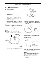
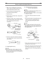
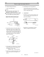
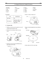
1.2 Boom length and angle detector
The Boom length and angle detector is installed
on the boom side, and uses the potentiometer
inside the detector to convert the extended boom
length and the angle of the boom relative to the
ground into an electric signal that is transmitted to
AML main body.
1.3 Outrigger extension width detector
It is installed on the rear end of the outrigger outer
case. The potentiometer in the detector converts
the outrigger extension width into the electric
signal and transmits it to AML main body.
1.4 Other detectors and switches
The outer detectors and switches convert the
crane operation modes and working conditions
into an electric signal that is transmitted to AML
main body.
1.5 AML (Load moment indicator) main body
1. AML main body calculates the moment being
generated on the crane based on signals from the
pressure sensor and the Boom length and angle
detector.
2. The calculation result is compared with the rated
moment and,when it reaches 90% and 100% of
the rating, AML sends alarm and auto. stop
signals, respectively, to prevent the crane from
being overloaded.
1.6 Overwind cutout (Anti-twoblock) device
The anti-twoblock device prevents damage to the
crane that would be caused by pulling the hook
block into the boom head. When the hook block
approaches the boom head, single top or jib, the
overwind cutout device sends a signal to AML,
which then stops any further crane action toward
the critical condition.
1.7 Solenoid valve
1. If AML malfunctions or if the actual moment
reaches 100% of the rated moment or the hook
block is over-hoisted, an electric signal (auto.
stop) is sent from AML main body to this valve.
2. When the solenoid valve is deenergizied, this
solenoid valve contents the vent line of the relief
valve mounted on the hydraulic pilot control valve
to the tank. The solenoid valve by allowing the
pressurized oil from the pump to escape through
the relief valve to the tank, therefore the crane
operation stops.
2. Description of system
Refer to the repair manual of AML-L.
Summary of Contents for TR-800XXL4
Page 47: ...B 9 B 9 Rotary Joint 27 W181 0440E Upper view A Lower view B...
Page 119: ...F 1 F 1 Winch System 1 WF02 0251E F 1 Winch System 1 General Hydraulic Circuit for Winch...
Page 135: ...G 1 G 1 Telescoping System 3 WG02 0321E Telescoping cylinder at select...
Page 143: ...G 2 G 2 Boom Five Section Boom G 2 11 W536 0761E 11...
Page 196: ...13 13 W701 0220E K 2 K 2 Air Conditioner K 2 4 Layout 4 1 Overall layout 4 345 107 61000...
Page 197: ...14 14 W701 0220E K 2 K 2 Air Conditioner K 2 4 2 Overall layout 0 345 110 73000...
Page 198: ...15 15 W701 0220E K 2 K 2 Air Conditioner K 2 4 3 Evaporator section 5 345 107 02000...
Page 199: ...16 W701 0220E K 2 K 2 Air Conditioner 5 Compressor Assy...
Page 200: ...17 17 W701 0220E K 2 K 2 Air Conditioner K 2 6 Evaporator Assy...
Page 201: ...18 18 W701 0220E K 2 K 2 Air Conditioner K 2 7 Condenser Assy...
Page 202: ...19 19 W701 0220E K 2 K 2 Air Conditioner K 2 8 Electric 8 1 Electric circuit 0 363 205 60030...
Page 203: ...20 20 W701 0220E K 2 K 2 Air Conditioner K 2 8 2 Main harness A...
Page 204: ...21 21 W701 0220E K 2 K 2 Air Conditioner K 2 8 3 Main harness B...
Page 222: ...39 K 2 K 2 K 2 Air Conditioner 39 W701 0220E 12 2Compressor diagnosis chart 1 2...
Page 223: ...40 K 2 K 2 K 2 Air Conditioner 40 W701 0220E Compressor diagnosis chart 2 2...
Page 224: ...K 2 K 2 Air Conditioner 41 W701 0220E 13 Troubleshooting...
Page 225: ...K 2 K 2 Air Conditioner 42 W701 0220E...
Page 226: ...K 2 K 2 Air Conditioner 43 W701 0220E...
Page 227: ...K 2 K 2 Air Conditioner 44 W701 0220E...
Page 228: ...K 2 K 2 Air Conditioner 45 W701 0220E...
Page 229: ...K 2 K 2 Air Conditioner 46 W701 0220E...
Page 237: ...L 1 L 1 Control System 2 WL02 0090E 2 General of pneumatic control devices Pneumatic Circuit...
Page 291: ...T 5 T 5 Air Dryer 26 W232 0032E Heater View A 39 C B B A 58 59 2 IW232 0030E03...
Page 370: ...8 8 WZ03 3300E Z 5 Z 5 Electric Circuit MDT Carrier Upper Z 5 IWZ03 3300E01...
Page 372: ...10 Z 6 Z 6 Electric Circuit MDT Carrier Lower Z 6 10 WZ03 3310E IWZ03 3310E01...
Page 400: ...38 Z 24 Z 24 Harness Lower Sub 38 WZ04 2450E Z 24 Z 24 Harness Lower Sub 2 349 310 00200...

