


H - 2
H - 2
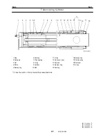
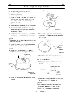
Boom Length and Angle Detector
4
W305-0451E
2. Disassembly and reassembly
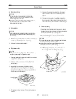
2.1 Removing the cord
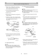
1. Remove the connector and the cord lock from the
end of the cord. Wind up the cord on the drum
slowly until no tension of the spiral spring is
applied on the cord.
2. Loosen the clamp and remove the cover (2 place).
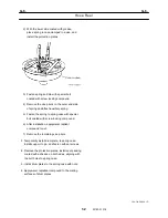
3. Disconnect the cable, potentiometer and angle
detector from the terminal, and remove the cover
and the cable together.
4. Loosen the set screw and remove the gear. Then
remove the screw and detach the speed reducer.
[NOTICE]
Remove the speed reducer straight upward. Do not
twist it while removing.
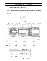
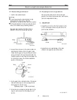
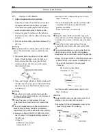
5. Remove the retaining ring and bolt, and separate
the case from the drum assembly.
[NOTICE]
Put match marks on the case and the plate to
identify the direction for removing the sub-cord.
IW305-0230E03
Retaining ring
Plate
Match marks
Sub-cord
Case
Bolt
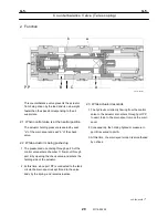
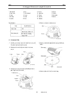
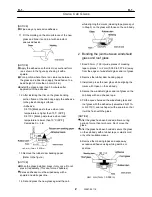
6. Remove the nut and separate the drum assy from
the plate.
IW305-0230E04
Drum assy
Plate
Nut
7. Remove the slip ring assy from the drum assy.
Then remove the solder that bonds the slip ring
and the cord.
IW305-0230E05
Cord
Slip ring assy
Slip ring assy
Core wire
Shield wire
8. Detach the whole old cord from the drum assy.
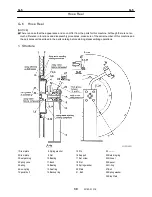
2.2 Installing the cord
1. Wind a yellow tape around the new cord as a
0-marker.
2. Pass the new cord through the hole of the drum
assy. Solder it on the slip ring assy.
[NOTICE]
Attach the cord core wire to the inner slip ring.
Attach the shield wire to the outer slip ring.
Completely insulate the soldered section.
Summary of Contents for TR-800XXL4
Page 47: ...B 9 B 9 Rotary Joint 27 W181 0440E Upper view A Lower view B...
Page 119: ...F 1 F 1 Winch System 1 WF02 0251E F 1 Winch System 1 General Hydraulic Circuit for Winch...
Page 135: ...G 1 G 1 Telescoping System 3 WG02 0321E Telescoping cylinder at select...
Page 143: ...G 2 G 2 Boom Five Section Boom G 2 11 W536 0761E 11...
Page 196: ...13 13 W701 0220E K 2 K 2 Air Conditioner K 2 4 Layout 4 1 Overall layout 4 345 107 61000...
Page 197: ...14 14 W701 0220E K 2 K 2 Air Conditioner K 2 4 2 Overall layout 0 345 110 73000...
Page 198: ...15 15 W701 0220E K 2 K 2 Air Conditioner K 2 4 3 Evaporator section 5 345 107 02000...
Page 199: ...16 W701 0220E K 2 K 2 Air Conditioner 5 Compressor Assy...
Page 200: ...17 17 W701 0220E K 2 K 2 Air Conditioner K 2 6 Evaporator Assy...
Page 201: ...18 18 W701 0220E K 2 K 2 Air Conditioner K 2 7 Condenser Assy...
Page 202: ...19 19 W701 0220E K 2 K 2 Air Conditioner K 2 8 Electric 8 1 Electric circuit 0 363 205 60030...
Page 203: ...20 20 W701 0220E K 2 K 2 Air Conditioner K 2 8 2 Main harness A...
Page 204: ...21 21 W701 0220E K 2 K 2 Air Conditioner K 2 8 3 Main harness B...
Page 222: ...39 K 2 K 2 K 2 Air Conditioner 39 W701 0220E 12 2Compressor diagnosis chart 1 2...
Page 223: ...40 K 2 K 2 K 2 Air Conditioner 40 W701 0220E Compressor diagnosis chart 2 2...
Page 224: ...K 2 K 2 Air Conditioner 41 W701 0220E 13 Troubleshooting...
Page 225: ...K 2 K 2 Air Conditioner 42 W701 0220E...
Page 226: ...K 2 K 2 Air Conditioner 43 W701 0220E...
Page 227: ...K 2 K 2 Air Conditioner 44 W701 0220E...
Page 228: ...K 2 K 2 Air Conditioner 45 W701 0220E...
Page 229: ...K 2 K 2 Air Conditioner 46 W701 0220E...
Page 237: ...L 1 L 1 Control System 2 WL02 0090E 2 General of pneumatic control devices Pneumatic Circuit...
Page 291: ...T 5 T 5 Air Dryer 26 W232 0032E Heater View A 39 C B B A 58 59 2 IW232 0030E03...
Page 370: ...8 8 WZ03 3300E Z 5 Z 5 Electric Circuit MDT Carrier Upper Z 5 IWZ03 3300E01...
Page 372: ...10 Z 6 Z 6 Electric Circuit MDT Carrier Lower Z 6 10 WZ03 3310E IWZ03 3310E01...
Page 400: ...38 Z 24 Z 24 Harness Lower Sub 38 WZ04 2450E Z 24 Z 24 Harness Lower Sub 2 349 310 00200...


