


28
W701-0220E
K - 2
K - 2
Air Conditioner
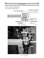
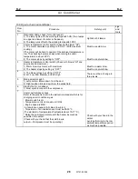
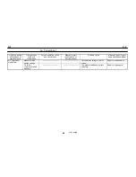
10.3 How to check air conditioner
Flow
No.
Procedure Safety
point
Jigs
and
tools
1
Illumination lamp check (for control panel)
1) The lamp lights with the working lamp switch ON. (Two lamps
on upper and lower of center in the panel.)
2) The lamp turns off with the working lamp switch OFF.
Lights both 2 lamps.
2
Cooler temperature control switch. (Check with blower "HI".)
1) The cooler operates by setting to "COOL". (With maximum
cooling.)
(The cooler will be hard to operate if the ambient temperature is
low. The checking becomes easy when raising the cabin
temperature to about 25°C.)
2) The cooler stops by setting to "OFF".
Must be a cold blow
Must be a natural blow.
3
Heater temperature control switch (Check with blower "HI" and
engine speed maximum.)
1) Warm blow must come with maximum.
2) The heater stops by setting to "OFF".
Must be a warm blow
Must be a natural blow.
4
1) The blower stops by setting to "OFF".
2) LO: Low, ME: Medium, and HI: High
There must be a change in
three levels
5
Mode selector switch
1) Left position: Blows down from the duct.
2) Right position: Blows down from the windshield.
6
Electric fan for condenser
1) Must synchronize with the compressor.
7
Cooler performance check
Refer to the graphic chart in the instruction manual which is for
charging an air conditioner gas.
- Blower switch is HI.
- Temperature control is maximum COOL.
- Engine speed is MAX.
- All doors are opened. (All closes in winter.)
- Tmperature of air inhalation vent must be 25-35 °C.
(The standard of temperatures fluctuate is about 10-17°C.)
* Raise the cabin temperature with the heater as much as
possible in the winter.
(Check with your hand that the cold blow is
output.---Compressor must be operating.)
Check with your hand in the
winter.
Avoid performing in the low
ambient temperature period
as much as possible.
Summary of Contents for TR-800XXL4
Page 47: ...B 9 B 9 Rotary Joint 27 W181 0440E Upper view A Lower view B...
Page 119: ...F 1 F 1 Winch System 1 WF02 0251E F 1 Winch System 1 General Hydraulic Circuit for Winch...
Page 135: ...G 1 G 1 Telescoping System 3 WG02 0321E Telescoping cylinder at select...
Page 143: ...G 2 G 2 Boom Five Section Boom G 2 11 W536 0761E 11...
Page 196: ...13 13 W701 0220E K 2 K 2 Air Conditioner K 2 4 Layout 4 1 Overall layout 4 345 107 61000...
Page 197: ...14 14 W701 0220E K 2 K 2 Air Conditioner K 2 4 2 Overall layout 0 345 110 73000...
Page 198: ...15 15 W701 0220E K 2 K 2 Air Conditioner K 2 4 3 Evaporator section 5 345 107 02000...
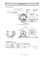
Page 199: ...16 W701 0220E K 2 K 2 Air Conditioner 5 Compressor Assy...
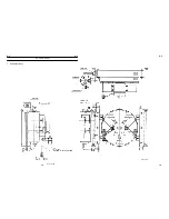
Page 200: ...17 17 W701 0220E K 2 K 2 Air Conditioner K 2 6 Evaporator Assy...
Page 201: ...18 18 W701 0220E K 2 K 2 Air Conditioner K 2 7 Condenser Assy...
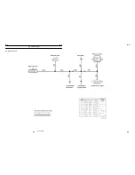
Page 202: ...19 19 W701 0220E K 2 K 2 Air Conditioner K 2 8 Electric 8 1 Electric circuit 0 363 205 60030...
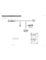
Page 203: ...20 20 W701 0220E K 2 K 2 Air Conditioner K 2 8 2 Main harness A...
Page 204: ...21 21 W701 0220E K 2 K 2 Air Conditioner K 2 8 3 Main harness B...
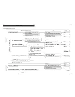
Page 222: ...39 K 2 K 2 K 2 Air Conditioner 39 W701 0220E 12 2Compressor diagnosis chart 1 2...
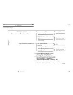
Page 223: ...40 K 2 K 2 K 2 Air Conditioner 40 W701 0220E Compressor diagnosis chart 2 2...
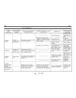
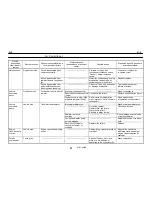
Page 224: ...K 2 K 2 Air Conditioner 41 W701 0220E 13 Troubleshooting...
Page 225: ...K 2 K 2 Air Conditioner 42 W701 0220E...
Page 226: ...K 2 K 2 Air Conditioner 43 W701 0220E...
Page 227: ...K 2 K 2 Air Conditioner 44 W701 0220E...
Page 228: ...K 2 K 2 Air Conditioner 45 W701 0220E...
Page 229: ...K 2 K 2 Air Conditioner 46 W701 0220E...
Page 237: ...L 1 L 1 Control System 2 WL02 0090E 2 General of pneumatic control devices Pneumatic Circuit...
Page 291: ...T 5 T 5 Air Dryer 26 W232 0032E Heater View A 39 C B B A 58 59 2 IW232 0030E03...
Page 370: ...8 8 WZ03 3300E Z 5 Z 5 Electric Circuit MDT Carrier Upper Z 5 IWZ03 3300E01...
Page 372: ...10 Z 6 Z 6 Electric Circuit MDT Carrier Lower Z 6 10 WZ03 3310E IWZ03 3310E01...
Page 400: ...38 Z 24 Z 24 Harness Lower Sub 38 WZ04 2450E Z 24 Z 24 Harness Lower Sub 2 349 310 00200...


