background image


W119-0212E 

E - 3 .  

E - 3 .

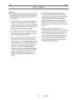
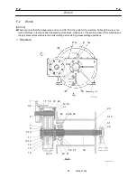
Counterbalance Valve (Elevating) 

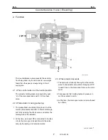
2. Function 

C

a

B

P.P

A

b

IW119-021003


  This counterbalance valve prevents the actuator 

from being driven by the load and its own weight 

faster than the speed corresponding to the oil 

supply rate. 

2.1  When control valve is at the neutral position 

  The actuator holding pressure is sealed by seat 

“a” of the main spool and seat “b” of the check 

valve. 

2.2  While actuator is being pushed up 

1. The pressurized oil entering through port A of the 

control valve enters chamber C, flows out through 

port B by opening the check valve, and enters the 

holding side of the actuator. 

2. At this time, since port PP is connected to the tank 

circuit, the main spool is kept forced to the valve 

body by the spring, and remains inactive. 

2.3  While actuator descends 

1. The hydraulic oil directly flowing from the control 

valve to the actuator also enters through port PP 

to exert force to the main spool to move the main 

spool. 

2. Consequently, the holding hydraulic pressure in 

port B is vented to port A. 

3. At this time, the main spool motion is smoothened 

by orifices. 


366-051-70000

Summary of Contents for TR-800XXL4

Page 1: ...Publication No GR 800XXL 1 S2 U 1E 01 Rough Terrain Crane TR 800XXL 4 Applicable Serial No 545870 545961 Model 2006 PRINTED IN JAPAN 0608 K Service Manual GR 800XXL 1 S2 U 1E...

Page 2: ...instructions in this manual are identified as DANGER WARNING CAUTION or NOTICE These terms are defined as follows NOTICE NOTICE indicates an important operational or maintenance procedure or condition...

Page 3: ...low the capacitors to discharge Pull out the ignition key and hang a tag saying Don t start the engine in the cab 6 Don t carry out maintenance while lifting the vehicle with only a jack or a hoist Su...

Page 4: ...uts fixing it don t apply too much force to it but check the part for the cause Only after relieving the cause proceed disassembling 7 Use lifting slings appropriate for the weight and characteristics...

Page 5: ...Spill or leak Review fire and explosion hazards before proceeding with clean up Use appropriate personal protective equipment during clean up Dike spill Prevent liquid from entering sewers waterways...

Page 6: ...he parts catalog for repair and maintenance of the crane in conjunction with this manual If the parts needs to be replaced check the disassemble units and sales units in the parts catalog before repla...

Page 7: ...ted Winch brake Automatic brake Neutral brake Winch Drum rotation indicator Touch type Option Weight Counterweight Removable type Load moment indicator AML AML L2C Auto stop solenoid valve energizing...

Page 8: ...cubic meter m 3 cubic inch in 3 cubic foot ft 3 gallon gal cubic inch in 3 liter lit L 1 0 000001 0 0610 0 0000353 1 231 3 785 1000000 1 61024 35 31 0 004329 1 0 01639 16 39 0 0000164 1 0 000579 0 264...

Page 9: ...3 0 1383 1 12 11 3 0 113 1 1525 0 01153 0 08333 1 Centigrade Fahrenheit F F F F F F 90 67 78 40 40 10 12 22 60 15 56 110 43 33 160 71 11 80 62 22 30 34 44 20 6 67 70 21 11 120 48 89 170 76 67 70 56 67...

Page 10: ...tem Winch System Boom Telescoping System Safety System Cab Control System Steering System Brake System Suspension System System Diagrams Data Adjustment and Checks B C D E F G H I J K L M N O P Q R S...

Page 11: ...Gear Pump B 3 Hydraulic Pump Gear Pump Emergency Steering Option B 4 Hydraulic Valve Emergency Steering Option B 5 Flow Control Valve B 6 Pressure Reducing Valve Pilot Pressure B 7 Solenoid Control V...

Page 12: ...B Outrigger System Outrigger System C 1 Jack Cylinder C 2 Pilot Check Valve Jack Cylinder Retracting Prevention C 3 Extension Cylinder C 4 UCHIDA C 5 TOKIMEC C 6 Solenoid Valve Slide Jack NACHI C 7 C...

Page 13: ...erbalance Valve Elevating E 3 E Winch system Winch System F 1 Winch F 2 Hydraulic Motor Winch F 3 Counterbalance Valve Winch F 4 F Hydraulic Valve Winch Brake Release F 5 Boom T elescoping system Tele...

Page 14: ...h Detector H 3 H Solenoid Valve Auto Stop H 4 Cab Crane Cab Glass K 1 Air Conditioner Option K 2 Hydraulic Motor Air conditioner Option K 3 Solenoid Valve Air conditioner Option K 4 K Control System C...

Page 15: ...on Refer to separate manual W561 0101E R Driving Axle Refer to separate manual W563 0052E Steering System Steering System S 1 Priority Valve S 2 Orbitrol S 3 Steering Cylinder S 4 Solenoid Valve Steer...

Page 16: ...3 Solenoid Valve Suspension Lock Check Release U 4 U Data Adjustment and Checks Hydraulic Pressure Setting Table Y 1 Air Pressure Setting Table Y 2 Air Bleeding Procedure Y 3 Electric Switch Adjustme...

Page 17: ...tion of Installation Location of Hydraulic Parts Upper Z 7 Location of Hydraulic Parts Lower Z 8 Location of Air Parts Z 9 Location of Electric Parts Inside Cab Z 10 Location of Electric Parts Swing T...

Page 18: ...Chapter Section GR 800 1 00211 2M2D North America Harness Swing Table Right Z 19 Harness Boom Z 20 Harness AML Upper Z 21 Harness Overwind Z 22 Harness Lower Main Z 23 Harness Lower Sub Z 24 Z Harness...

Page 19: ...e 13 2 Air bleeding procedure 15 B 4 Hydraulic Pump Gear Pump Emergency Steering 16 1 Structure 16 B 5 Hydraulic Valve Emergency Steering Option 17 1 Structure 17 B 6 Flow Control Valve 19 1 Structure...

Page 20: ...ve Jib Set 51 1 Structure 51 B 14 Pilot Check Valve Jib Set 57 1 Structure 57 B 15 Solenoid Valve Oil Cooler 58 1 Structure 58 B 16 Hydraulic Motor Oil Cooler 60 1 Structure 60 2 Air bleeding procedur...

Page 21: ...or the emergency steering circuit 2 The double variable displacement pump supplies oil to the circuits of elevating telescoping main winch and auxiliary winch This double variable displacement pump is...

Page 22: ...elevating telescoping and the relief valve main winch auxiliary winch When the PTO switch is turned on the solenoid valve for automatic stop is shifted making the condition of this circuit onloaded 2...

Page 23: ...rcuits Pressurized oil reduced by the sequence valve is supplied to the circuit for the pilot pressure 2 The pilot pressure is supplied to the swing brake release circuit main winch brake release circ...

Page 24: ...er from the parts for this machine Although there is not so much difference in functions and disassembly procedures make sure of the serial number of this machine and the part sales unit described in...

Page 25: ...nder spring 211 Shoe plate 212 Swash plate 214 Tilting bush 251 Support 261 Seal cover F 262 Seal cover R 271 Pump casing 312 Valve block 313 Valve plate R 314 Valve plate L 401 Hex socket head bolt 4...

Page 26: ...2 789 535 808 886 717 406 774 111 261 824 127 123 710 251 490 212 211 153 156 157 314 312 792 953 IW101 0270E02 Apply Shealub L101 to the oil seal surface circumferential Apply adhesive No 1305N of Th...

Page 27: ...Double Variable Displacement Pump 7 W101 0272E 901 466 725 114 885 313 141 467 728 271 401 262 954 719 124 151 152 113 406 710 Valve plate for clockwise rotation IW101 0270E03 Enlarged view of the ma...

Page 28: ...B 2 B 2 Hydraulic Pump Double Variable Displacement Pump 8 W101 0272E IW101 012004 962 412 924 627 701 801 624 651 724 652 621 496 887 629 402 625 728 Z Regulator...

Page 29: ...k lever 614 Center plug 621 Compensator piston 624 Spring seat 625 Compensator spring 627 Spring seat 629 Spring case 651 Sleeve 652 Spool 701 O ring 708 O ring 724 O ring 728 O ring 755 O ring 801 Nu...

Page 30: ...B 2 B 2 Hydraulic Pump Double Variable Displacement Pump 10 W101 0272E 2 Theory of operating of regulator section...

Page 31: ...he servo piston The oil flowing to area A applies leftward pressure to the compensation piston When the pump pressure is below a certain level the spool does not move because the leftward force of the...

Page 32: ...he left and seating areas C and E open where the Hydraulic powers of the small and large diameter ends of the servo piston are balanced When the pump pressure decreases the compensation spring pushes...

Page 33: ...fer from the parts for this machine Although there is not so much difference in functions and disassembly procedures make sure of the serial number of this machine and the part sales unit described in...

Page 34: ...ing box 3 Bearing box 6 Front cover 7 Side plate 8 Backup ring 9 Rubber string 10 Hex socket head bolt 12 O ring 13 Drive gear 14 Driven gear 15 Rear cover 16 Dowel pin 17 Oil seal 18 Oil seal 19 Reta...

Page 35: ...2 Bearing box 3 Bearing box 6 Front cover 7 Side plate 8 Backup ring 9 Rubber string 10 Hex socket head bolt 12 O ring 13 Drive gear 14 Driven gear 15 Rear cover 16 Dowel pin 2 Air bleeding procedure...

Page 36: ...part sales unit described in the parts catalog before starting disassembling operations 1 Structure 25 3 21 23 13 21 1 4 22 32 31 12 5 11 22 2 C D A B C C C IW101 014001 1 Front cover 2 Body 3 Drive g...

Page 37: ...there is not so much difference in functions and disassembly procedures make sure of the serial number of this machine and the part sales unit described in the parts catalog before starting disassemb...

Page 38: ...3 0260E02 14 7 10 B 11 3 11 C 4 8 13 5 9 6 2 1 A 12 Y Y X X 1 Body 2 Check valve 3 Spool 4 Check valve 5 Cover 6 Spring 7 Spring 8 Spring 9 O ring 10 Plug 11 Plug 12 Plug 13 Spring washer 14 Hexagon s...

Page 39: ...s make sure of the serial number of this machine and the part sales unit described in the parts catalog before starting disassembling operations 1 Structure IW114 0130E01 PA PB T IW114 0130E03 7 4 2 1...

Page 40: ...number of this machine and the part sales unit described in the parts catalog before starting disassembling operations 1 Structure IW120 0120E01 DR A2 P A1 IW120 0120E02 P A1 A2 DR 1 1 2 3 4 5 6 7 8...

Page 41: ...ial number of this machine and the part sales unit described in the parts catalog before starting disassembling operations 1 Structure T A B P Sol a1 Sol b1 G R1 L IW112 015001 R1 A T P L L G B Sol a1...

Page 42: ...8 B 8 Solenoid Control Valve Outrigger 22 W112 0152E 2 1 6 5 7 4 P G R1 3 2 IW112 015003 P cover assy illustrated as 10 on page 21 1 Cover 2 O ring 3 O ring 4 Shim 5 Plug 6 Plug assy 7 Relief valve as...

Page 43: ...0152E 13 11 2 1 8 3 4 10 12 6 9 14 7 5 IW112 011004 T P 1 Body 2 Plunger 3 Body 4 Poppet 5 Adjuster screw 6 Nut 7 Spring 8 Spring 9 Shim 10 O ring 11 O ring 12 O ring 13 Backup ring 14 Cap P cover as...

Page 44: ...l Valve Outrigger 24 W112 0152E Sol a1 Sol b1 A B 10 9 1 2 7 7 8 6 3 5 4 IW112 015004 1 Body 2 Spool 3 Plug 4 Plunger 5 Spring 6 O ring 7 O ring 8 O ring 9 Shim 10 Pilot cover assy Body assy 1 2 illus...

Page 45: ...IW112 015005 0 366 460 20000 1 Cover 2 Plug 3 Spool 4 Spring 5 O ring 6 Spring seat 7 Hexagon socket head bolt 8 Plug 9 Solenoid DC24V 10 Orifice 11 O ring 12 O ring 13 Hexagon socket head bolt 14 He...

Page 46: ...much difference in functions and disassembly procedures make sure of the serial number of this machine and the part sales unit described in the parts catalog before starting disassembling operations...

Page 47: ...B 9 B 9 Rotary Joint 27 W181 0440E Upper view A Lower view B...

Page 48: ...7 1 to secure the plate 18 M8 11 8 13 7 9 10 21 1 to secure the slip ring ass y 1 M6 4 4 5 4 3 5 4 25 1 M8 23 5 27 5 17 20 29 16 24 12 17 1 Apply thread locking agent equivalent to THREE BOND 1401 to...

Page 49: ...OUT Lower Rc3 8 49 69 36 51 Attention 1 Face the mark toward FRONT 2 Apply water proof sealant equivalent to THREE BOND 4101 Do not apply grease 3 Apply thread locking agent equivalent to THREE BOND 1...

Page 50: ...nt 30 W181 0440E Slip ring Assy A B A B 31 IW181 0260E03 27 26 B B IW181 0260E04 29 P IW181 0260E05 T1 D E F D E F C C 22 20 31 7 3 2 11 12 6 3 7 1 8 16 17 18 19 24 23 15 21 28 9 4 10 12 5 13 30 25 P...

Page 51: ...ase 16 Dry lock nut 17 Coned disc spring 18 Guide 19 O ring 20 Potentiometer 21 Cover 22 Packing 23 Lever 24 Pin 25 Guide 26 Air breather 27 Hose joint 28 Hose band 29 Hexagon socket set screw 30 Mach...

Page 52: ...2 6 5 3 2 3 4 1CC 4 3 1DD 1 2 1AA 2 1 1BB 12 6 12 13 5 13 14 4 614 8 3 8 9 2 9 10 1 10 27 12 627 28 11 628 29 10 629 30 630 20 21 7 21 22 6 22 4 24 5 15 4 615 16 3 16 18 2 618 19 1 19 3 2 1 6 5 4 3 2...

Page 53: ...E13 Stamp mark Slip ring assy 3 Turn the potentiometer shaft using a slotted screwdriver so that the resistance between the upper terminals 1 and 2 is minimum between 1 ohm and 15 ohm Leave the termin...

Page 54: ...ng Winch NOTICE There is a case that the appearance and so on differ from the parts for this machine Although there is not so much difference in functions and disassembly procedures make sure of the s...

Page 55: ...evating Telescoping Winch 35 W134 0271E C1 C2 Vent down down extending lowering Aux winch up Main winch up Telescoping retracting Elevating raising a3 a4 b3 b4 C3 B1 B2 B3 B4 T2 A1 A2 A3 A4 P2 T1 a1 a...

Page 56: ...lve Elevating Telescoping Winch 36 W134 0271E Thread size and tightening torque Tightening torque Sign port Thread size N m ft lbf C1 C2 C3 a1 a2 a3 a4 b1 b2 b3 b4 Vent G1 4 29 4 22 A3 B3 A4 B4 G3 4 1...

Page 57: ...B 10 B 10 Hydraulic Pilot Control Valve Elevating Telescoping Winch 37 W134 0271E B A B A 14 13 IW134 011012 Aux winch Main winch Telescoping Elevating Cross section of whole body...

Page 58: ...B 10 B 10 Hydraulic Pilot Control Valve Elevating Telescoping Winch 38 W134 0271E C D E F G C D E F G 1 2 3 4 7 16 12 8 12 9 A A Aux winch Main winch Telescoping Elevating IW134 0270E03...

Page 59: ...2 Telescoping selector valve 3 Elevating selector valve 4 End cover 5 O ring 6 O ring 7 Hex socket head bolt 8 Main relief valve 9 Main relief valve 12 Hex socket head bolt 13 Plug 14 O ring 15 Plug...

Page 60: ...Telescoping Winch IW134 0270E04 29 30 6 2 4 20 19 21 22 1 25 24 23 13 18 17 15 28 27 26 28 14 7 11 10 9 8 12 23 24 25 16 17 Overload relief valve C C Aux winch D D Main winch IW134 0110E07 18 17 15 2...

Page 61: ...k valve 20 Spring check valve 21 Plug check valve 22 O ring 23 Hex socket head bolt 24 Plain washer 25 Spring washer 26 Plug 27 O ring 28 Plug 29 Steel ball 30 Hex socket set screw Thread size and tig...

Page 62: ...ttle valve 16 O ring 17 Orifice 18 Spring flow control valve 19 Plug 20 O ring 21 Check valve 22 Spring check valve 23 Plug check valve 24 O ring 25 Hex socket head bolt 26 Plain washer 27 Spring wash...

Page 63: ...Spool end 12 Pilot cover 13 Pilot cover 14 Orifice 15 Spring flow control valve 16 Plug 17 O ring 18 Plug 19 O ring 20 Hex socket head bolt 21 Plain washer 22 Spring washer 23 Plug Thread size and tig...

Page 64: ...ring 7 Packing 8 Body 9 O ring 10 Cap nut 11 Adjust screw 12 O ring 13 Nut 14 Body 15 Spring 16 Valve 17 Valve seat 18 O ring 19 Seal lead 20 Tie up wire Thread size and tightening torque Tightening...

Page 65: ...6 O ring 7 O ring 8 Body 9 Valve 10 Spring 11 Adjust screw 12 O ring 13 Nut 14 Cap nut 15 Tie up wire 16 Seal lead Thread size and tightening torque Tightening torque Sign port Thread size N m ft lbf...

Page 66: ...achine Although there is not so much difference in functions and disassembly procedures make sure of the serial number of this machine and the part sales unit described in the parts catalog before sta...

Page 67: ...Tightening torque Sign port Thread size N m ft lbf 1 M24 1 5 58 8 68 6 43 4 50 6 1 Body 2 Filter 3 Filter retainer 4 Back pressure regulating valve 5 Pressure reducing valve 6 Hexagon socket head bolt...

Page 68: ...7 11 10 8 6 3 5 12 2 13 9 1 4 1 Body 2 Spool 3 O ring 4 Plug 5 Spring seat 6 Spring 7 Adjust screw 8 Body 9 O ring 10 Nut 11 Cap nut 12 O ring 13 O ring Pressure reducing valve illustrated as 5 in th...

Page 69: ...ures make sure of the serial number of this machine and the part sales unit described in the parts catalog before starting disassembling operations 1 Structure IW121 067001 A2 T P A1 T1 IW121 067002 A...

Page 70: ...01 802 326 324 P A T 311 Spool 312 Sleeve 324 Spring 326 Retaining ring 361 O ring 362 O ring 363 O ring 801 Solenoid valve 802 Seal nut 861 O ring Thread size and tightening torque Tightening torque...

Page 71: ...ffer from the parts for this machine Although there is not so much difference in functions and disassembly procedures make sure of the serial number of this machine and the part sales unit described i...

Page 72: ...B2 B1 A2 A1 P P T P OUT OUT P P IN A C C D D A B B 18 Name plate 21 Tigh rod 27 Plug 29 Hexagon socket head bolt 31 Nut 32 Ribbet screw 33 Ball 38 O ring Thread size and tightening torque Tightening t...

Page 73: ...8 28 34 19 38 23 27 33 25 44 35 33 33 37 8 9 35 33 16 34 19 38 27 23 20 22 7 8 A A 6 Collar 7 Spring folder 8 Plug 9 Spring 16 Solenoid 19 Body 20 Spring 22 Spring 23 Filter 25 Spool end 27 Plug 28 He...

Page 74: ...B 13 B 13 Solenoid Control Valve Jib Set 54 W112 0222E B B IW112 0220E04 14 35 14 24 17 43 15 35 14 Spol 15 Housing 17 Housing plunger 24 Housing 35 O ring 43 O ring...

Page 75: ...B 13 B 13 Solenoid Control Valve Jib Set 55 W112 0222E IW112 0220E05 P T C C IW112 0220E06 D D C O...

Page 76: ...lve Jib Set IW112 0220E07 42 12 2 41 1 40 10 4 30 3 36 5 13 11 39 1 Spring 2 Needle valve 3 Nut 4 Gasket 5 Spring 10 Housing 11 Sleeve 12 Sleeve 13 Poppet 30 Screw 36 O ring 39 O ring 40 O ring 41 O r...

Page 77: ...ake sure of the serial number of this machine and the part sales unit described in the parts catalog before starting disassembling operations 1 Structure B A D C IW115 027001 B D C A IW115 027002 7 6...

Page 78: ...ctions and disassembly procedures make sure of the serial number of this machine and the part sales unit described in the parts catalog before starting disassembling operations 1 Structure a e b f P A...

Page 79: ...11 2 T2 T1 3 1 Body 2 Plug 3 Spool 7 Spring seat 8 Square ring 9 O ring 11 Spring 12 Solenoid DC24V 15 Hexagon socket head bolt Thread size and tightening torque Tightening torque Sign port Thread siz...

Page 80: ...2 012001 1 Front case 2 Rear case 3 Shaft 4 Cylinder block 5 Piston retainer 7 Spherical retainer 8 Spherical pin 10 Collar 12 Spring 13 Straight key 14 Plain washer 16 Oil seal 17 Needle bearing 19 T...

Page 81: ...les unit described in the parts catalog before starting disassembling operations 1 Structure 1 Spring pin 2 plate 3 Plain bearing 4 Ring seal 5 O ring 6 Piston 7 Cylinder 8 Rod 9 Rod cover 10 Plain be...

Page 82: ...of this machine and the part sales unit described in the parts catalog before starting disassembling operations 1 Structure 1 Cylinder 2 Split pin 3 Nut 4 Piston 5 Plain bearing 6 O ring 7 Rod 8 Rod...

Page 83: ...hine and the part sales unit described in the parts catalog before starting disassembling operations 1 Structure P3 P2 P1 S P IW116 012001 1 P1 P2 P3 S 8 2 5 4 3 6 7 IW116 012002 Thread size and tight...

Page 84: ...ve Jack Cylinder Retracting Prevention 4 1 Structure 4 C 4 Extension Cylinder 5 1 Structure 5 C 5 Solenoid Valve Slide Jack UCHIDA 6 1 Structure 6 C 6 Solenoid Valve Slide Jack TOKIMEC 7 1 Structure 7...

Page 85: ...lenoid valve to enter the cylinders 3 At this time back pressure is generated in the return oil by the pilot check valve The return oil then passes through the solenoid control valve and returns to th...

Page 86: ...nding retracting and the four solenoid valves slide jack are switched according to the outputs from the multiplex data transmitter lower The outputs to the four solenoid valves slide jack are transmit...

Page 87: ...t sales unit described in the parts catalog before starting disassembling operations 1 Structure 1 Cylinder 2 Rod 3 Bolt 4 Spring washer 5 Bolt 6 Stopper 7 Spring pin 8 Piston 9 Packing 10 Backup ring...

Page 88: ...sassembly procedures make sure of the serial number of this machine and the part sales unit described in the parts catalog before starting disassembling operations 1 Structure B 5 4 6 7 8 2 3 1 A C D...

Page 89: ...procedures make sure of the serial number of this machine and the part sales unit described in the parts catalog before starting disassembling operations 1 Structure 1 Cylinder 2 Nut 3 Seal ring 4 Pis...

Page 90: ...er of this machine and the part sales unit described in the parts catalog before starting disassembling operations 1 Structure A B P T IW121 026001 IW121 0542E01 Connector IW121 026003 11 9 T2 7 3 8 1...

Page 91: ...ts catalog before starting disassembling operations 1 Structure A B P T IW121 026001 IW121 0542E01 Connector 12 1 2 3 4 5 6 7 8 9 10 11 A T P T B IW121 027001 Note Install the centering washer 10 with...

Page 92: ...and the part sales unit described in the parts catalog before starting disassembling operations 1 Structure A B P T IW121 026001 IW121 0542E01 Connector T T A B 10 16 7 14 8 9 6 15 4 3 13 2 1 IW121 0...

Page 93: ...sure of the serial number of this machine and the part sales unit described in the parts catalog before starting disassembling operations 1 Structure P1 P2 C B IW116 011001 P1 P2 C B 1 6 5 7 4 3 8 9...

Page 94: ...ng Assmbly 3 1 Structure 3 2 Swing bearing mounting bolt 4 2 1 Bearing Inner ring bolts 4 2 2 Bearing outer ring bolts 5 D 3 Hydraulic Pilot Control Valve Swing 6 1 Structure 6 D 4 Hydraulic Motor Swi...

Page 95: ...valve are connected at the two points having the same symbols such as a5 and b5 1 The swing operation is controlled by the hydraulic pilot method The pilot pressure from the remote control valve contr...

Page 96: ...valve high pressure is activated at low pressure only when the swing control lever is located at the neutral position 4 Circuit for swing automatic stop The right swing proportional control valve the...

Page 97: ...unctions and disassembly procedures make sure of the serial number of this machine and the part sales unit described in the parts catalog before starting disassembling operations 1 Structure NOTICE Ap...

Page 98: ...he rear of the carrier Apply torque control agent to the threaded sections of the bolts Install the plain washer orienting its chamfer on the internal periphery as shown below Thread size and tighteni...

Page 99: ...tall the plain washer orienting its chamfer on the internal periphery as shown below Thread size and tightening torque Tightening torque Sign port Thread size N m ft lbf 1 42 points 2 3 points 5 2 poi...

Page 100: ...he parts for this machine Although there is not so much difference in functions and disassembly procedures make sure of the serial number of this machine and the part sales unit described in the parts...

Page 101: ...ontrol Valve Swing 7 W134 0123E Thread size and tightening torque Tightening torque Sign port Thread size N m ft lbf P R G1 200 240 145 174 AM BM G3 4 150 180 108 130 G Pa Pb Pa Pb Pi1 Pi2 G1 4 34 38...

Page 102: ...ve Swing 8 W134 0123E A B A B AM RV BM Dr G P RB RA Sol 1 Sol 4 Pi2 Pa Pi1 Pb Sol 3 Sol 2 706 253 263 702 703 351 152 701 701 151 352 353 IW134 012003 AM RV BM Dr G P Sol 1 Sol 4 IW134 012007 Cross se...

Page 103: ...Control Valve Swing 9 W134 0123E C C Dr P R G C2 C1 152 414 413 401 450 412 411 415 151 IW134 012004 A A AM RA CA2 152 644 643 642 641 661 IW134 012005 B B Cross section along the line A A Cross sect...

Page 104: ...BM CB1 CA1 AM Pi1 Pb Sol 2 Sol 3 Pi2 231 211 212 234 235 C C 561 511 521 551 101 251 512 522 562 552 241 251 252 221 252 152 201 243 242 222 261 261 Pa IW134 012006 Pi1 Pb Sol 2 Sol 3 Pi2 Pa IW134 01...

Page 105: ...Cap 552 Plug 561 O ring 562 O ring 641 Spring seat 642 Spring 643 Steel ball 644 Seat 661 O ring 701 Relief valve 702 Solenoid relief valve 703 Relief valve 706 Solenoid valve DC24V Thread size and ti...

Page 106: ...in functions and disassembly procedures make sure of the serial number of this machine and the part sales unit described in the parts catalog before starting disassembling operations 1 Structure PB D...

Page 107: ...1 Hex socket head bolt 432 Stop ring 433 Stop ring 437 Iocking ring 438 Iocking ring 443 Roller bearing 444 Roller bearing 451 Spring pin 464 Plug 471 O ring 472 O ring 485 O ring 491 Oil seal 702 Bra...

Page 108: ...s machine Although there is not so much difference in functions and disassembly procedures make sure of the serial number of this machine and the part sales unit described in the parts catalog before...

Page 109: ...US 3 8 L Do not disassemble the king pins 8 27 nor spacer 13 1 Spur gear 2 Retainer 3 Roller bearing 4 Casing 5 Oil seal 6 Ball bearing 7 Plug 8 King pin 9 Carrier 10 Bearing washer 11 Needle bearing...

Page 110: ...System 1 1 General 1 E 2 Elevating Cylinder 3 1 Structure 3 E 3 Counterbalance Valve Elevating 5 1 Structure 5 2 Function 7 2 1 When control valve is at the neutral position 7 2 2 While actuator is b...

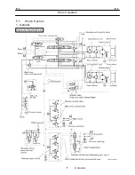
Page 111: ...E 1 E 1 Elevating System 1 WE02 0200E E 1 Elevating System 1 General Hydraulic Circuit for Boom Elevating Remote Control Pressure Vent...

Page 112: ...y the relief valve elevating telescoping The maximum pressure in the boom lowering circuit is regulated by the overload relief valve activated at low pressure to prevent the boom from hunting 3 Circui...

Page 113: ...appearance and so on differ from the parts for this machine Although there is not so much difference in functions and disassembly procedures make sure of the serial number of this machine and the part...

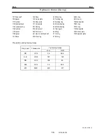
Page 114: ...Dust seal 16 Retainer 17 Spring washer 18 Bolt 19 Support 20 Fitting 21 O ring 22 Fitting 23 O ring 24 Pipe 25 Pipe 26 T fitting 27 Pipe 28 Clamp assy 29 Sleeve 30 Bolt 31 Spring washer 32 Counter ba...

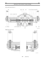
Page 115: ...ore starting disassembling operations 1 Structure IW119 021001 B A P P B P P A 7 6 5 4 2 6 2 5 2 3 2 4 2 9 2 10 2 11 2 12 2 13 2 14 2 2 2 1 2 16 2 15 1 2 8 3 7 3 8 3 6 3 5 3 4 3 3 3 1 3 2 2 7 IW119 02...

Page 116: ...ing 6 W119 0212E Thread size and tightening torque Tightening torque Sign port Thread size N m ft lbf A G3 4 167 123 P P G3 8 49 36 2 1 177 196 130 145 2 15 127 147 94 108 3 1 108 127 80 94 3 7 59 78...

Page 117: ...oil entering through port A of the control valve enters chamber C flows out through port B by opening the check valve and enters the holding side of the actuator 2 At this time since port PP is connec...

Page 118: ...Air bleeding procedure 8 F 4 Counterbalance Valve Winch 9 1 Structure 9 2 Function 10 2 1 Balancing and holding functions 10 2 2 Overload relief function 10 3 Principle of operation 11 3 1 When contro...

Page 119: ...F 1 F 1 Winch System 1 WF02 0251E F 1 Winch System 1 General Hydraulic Circuit for Winch...

Page 120: ...2 WF02 0251E F 1 F 1 Winch System Boom Telescoping Auxiliary Hoist 545522 Boom Telescoping Auxiliary Hoist 545523 Remote Control Pressure Vent...

Page 121: ...so as to assure a smooth hoist down movement In case of sudden stoppage of hoist down movement the relief valve integrated in the counterbalance valve operates to protect the hydraulic motor for the m...

Page 122: ...e is not so much difference in functions and disassembly procedures make sure of the serial number of this machine and the part sales unit described in the parts catalog before starting disassembling...

Page 123: ...1 gal 4 L Do not disassemble the sleeve 41 1 Bracket 3 Bolt 4 Spring washer 5 Oil seal 7 Bearing retainer 8 Ball bearing 9 Nut 10 Washer 11 Collar 12 Bolt 13 Spring washer 14 Drum gear 15 Collar 16 B...

Page 124: ...nce in functions and disassembly procedures make sure of the serial number of this machine and the part sales unit described in the parts catalog before starting disassembling operations 1 Structure T...

Page 125: ...4 101 403 443 106 431 113 124 301 444 402 472 703 710 741 742 720 706 404 702 707 471 122 123 121 114 485 464 111 131 697 451 303 401 761 762 463 432 705 701 473 476 IW102 013003 A 720 773 771 772 A I...

Page 126: ...g 472 O ring 473 O ring 476 O ring 485 O ring 491 Oil seal 697 O ring 701 Brake cover 702 Brake piston 703 Coupling 705 Brake spring 706 O ring 707 O ring 710 Brake shim 720 Brake casing 741 Separater...

Page 127: ...disassembly procedures make sure of the serial number of this machine and the part sales unit described in the parts catalog before starting disassembling operations 1 Structure IW119 0500E01 B1 A1 B...

Page 128: ...torque Tightening torque Sign port Thread size N m ft lbf 151 152 G3 8 69 79 51 58 171 M12 64 74 47 54 252 G1 4 34 38 25 28 253 G1 4 34 38 25 28 256 M10 14 18 10 13 271 273 M12 88 108 65 80 551 M33 1...

Page 129: ...alve 3 3 Hoisting down 1 As oil is sent to port B by the control valve it flows to the motor via port B1 2 The return oil from the motor is blocked at port A1 to raise the pressure at port B 3 This pr...

Page 130: ...ne and the part sales unit described in the parts catalog before starting disassembling operations 1 Structure IW123 020001 B1 P1 P2 Dr AC B2 T IW123 020002 B1 B2 T 4 10 2 6 7 5 2 3 8 1 P1 P2 Dr AC 9...

Page 131: ...m 17 3 2 Slide plate 17 3 3 Sheave 17 3 4 Boom telescoping wire rope 17 4 Reassembly 17 4 1 Greasing 17 4 2 Install anti buckling bolts for telescoping cylinder 17 4 3 Installing lower slide plates 18...

Page 132: ...ion 29 2 1 When control valve is at the neutral position 29 2 2 While actuator is being pushed up 29 2 3 While actuator descends 29 G 6 Hose Reel 30 1 Structure 30 2 Dismounting 31 3 Mounting 31 4 Dis...

Page 133: ...G 1 G 1 Telescoping System 1 WG02 0321E G 1 Telescoping System 1 General Hydraulic Circuit for Boom Telescoping 2M2D Boom Telescoping Auxiliary Hoist 545522...

Page 134: ...G 1 G 1 Telescoping System 2 WG02 0321E Boom Telescoping Auxiliary Hoist 545523 Remote Control Pressure Vent...

Page 135: ...G 1 G 1 Telescoping System 3 WG02 0321E Telescoping cylinder at select...

Page 136: ...iliary hoist switch the pilot circuit from the remote control valve boom telescoping auxiliary hoist control lever to the hydraulic pilot control valve to either the boom telescoping pilot circuit or...

Page 137: ...e and delivering the pressurized oil from the hydraulic pump to the selector valve 2 The pressurized oil is sent to the No 1 telescoping cylinder making the 2nd boom section extend 3 After the 2nd boo...

Page 138: ...ion of the 3rd boom section 3 At the same time the 4th and top boom sections retract by the wire rope mechanism 4 When the No 2 telescoping cylinder is almost fully retracted the boom full retraction...

Page 139: ...ection travel L2 No 2 cylinder stroke F3 3rd boom section force No 2 cylinder force W4 4th boom section weight Balance of force F3 2W4 Equation of workload W4 E4 F3 E3 4 3 4 4 3 3 4 W E W 2 W E F E 2E...

Page 140: ...L2 No 2 cylinder stroke F3 3rd boom section force No 2 cylinder force WT Top boom section weight Balance of force T T 3 W 3 2 W 6 F Equation of workload WT R5 F3 R3 T 3 T T 3 3 5 W R W 3 W R F R 3R3 3...

Page 141: ...oad W4 R4 F5 R5 5 4 5 4 4 5 5 4 R 3 2 W R 3 W 2 W R F R From equation b 2 4 L 3 3 2 R 2L2 4th boom section travel R4 2L2 3 3rd boom section Retracted by No 2 cylinder 3rd boom section travel R3 L2 4 2...

Page 142: ...hat the appearance and so on differ from the parts for this machine Although there is not so much difference in functions and disassembly procedures make sure of the serial number of this machine and...

Page 143: ...G 2 G 2 Boom Five Section Boom G 2 11 W536 0761E 11...

Page 144: ...pring washer 87 Plain washer 88 Support 89 Guide 90 Pin 91 Bolt 92 Pin 93 Pin 94 Sheave assy 95 Bolt 96 Plate 97 Spacer 98 Spacer 99 Pin 100 Split pin 101 Pin 102 Bolt 103 Bolt 104 Set screw 105 Plate...

Page 145: ...es 2 pieces and the hose leading to the hose reel from the telescoping cylinder NOTICE To prevent the hose reel from spinning attach a wire to the hose to the pipe sleeve of the hose and secure the wi...

Page 146: ...of the rear end of the 3rd boom section by loosening the bolt 1 and remove the pin and sheave assy by loosening the nut 5 Remove the pin from the rear end of the top boom section by loosening the bol...

Page 147: ...re rope for 4th boom section extension Hexagon socket head bolt L4 2 Lift up the rear end of the telescoping cylinder slightly using a crane and pull out the connecting pin that connects the 3rd boom...

Page 148: ...boom section retraction Jig Top boom section IW536 0620E15 4 After removing the retainer on the top of the 4th boom section head and removing the slide plate pull out the top boom section by approx 1...

Page 149: ...e diameter reduction exceeding 7 of the nominal diameter Evidence of any heat damage from any cause 4 Reassembly 4 1 Greasing When installing unplated pins apply grease beforehand Apply TNR 2 Grease s...

Page 150: ...m rear end Place shims so that the total clearance distributed to right and left is 0 5 mm 2 Upper clearance on boom rear end Place shims that the lateral deviation of center is 1 5 mm and vertical de...

Page 151: ...Over right Over left Other conditions Free from solar heat and wind 1 The hook displacement A in sketch under the above test conditions under no load must be brought within 200mm 7 9 in in all boom di...

Page 152: ...3 G 3 Jib G 3 20 W537 0102E 20 G 3 Jib 1 Structure 1 1 Location of Jib Applicable serial No 545419 545430 475327 1 545410 475326 2 545419 545430 475330 3 545419 545457 475330 4 545511 475349 437366 5...

Page 153: ...rt 14 Plate 15 Bolt 16 Nut 17 Plain washer 18 Support 19 Pin assy 20 Support 21 Support assy 22 Support assy 23 Support assy 24 Plate 25 End 26 Pin 27 Split pin 28 Plain washer 29 Clamp 30 Flange nut...

Page 154: ...G 3 G 3 Jib G 3 22 W537 0102E 22 1 2 Jib main body Applicable serial No 545410 475326 1 545410 475326 2 545410 475326 3 545419 545457 475330 4 545511 475349 437353 5...

Page 155: ...16 Spacer 17 Sheave assy 18 Plate 19 Pin 20 21 Link 22 Plate 23 Plate 24 Plate 25 Pin 26 Plain washer 27 Split pin 28 Stopper 29 Roller assy 30 Spacer 31 Pin 32 Bar 33 Pin 34 Split pin 35 Plate 36 Pi...

Page 156: ...the support and spring pin is 2 mm 0 08 in while the jib 1 supports the jib 2 X Jib 1 2 connecting spring pin Jib 1 Jib 2 IW537 0100E07 Support Spring pin 2 2 Adjusting jib inclination In order to fac...

Page 157: ...ove a shim t0 6 mm t0 02 in one by one from the slide plate on the support on the boom rear end until the pin can be inserted and removed easily 3 Add or remove shims t0 6 mm t0 02 in on the support o...

Page 158: ...assembly procedures make sure of the serial number of this machine and the part sales unit described in the parts catalog before starting disassembling operations 1 Structure 1 No 1 cylinder 2 No 2 cy...

Page 159: ...in 3 Nut 4 Piston 5 Backup ring 6 Packing 7 Plain bearing 8 O ring 9 Cylinder 10 Rod 11 O ring 12 Rod cover assy 13 Support 14 Damper ring 15 Packing 16 Backup ring 17 Plain bearing 18 Dust seal 31 O...

Page 160: ...escribed in the parts catalog before starting disassembling operations 1 Structure B A C IW119 022001 IW119 022002 6 5 4 10 9 1 8 12 11 3 2 7 20 14 13 15 16 17 19 18 B C A M 1 Body 2 O ring 3 Backup r...

Page 161: ...d oil entering through port A of the control valve enters chamber C flows out through port B by opening the check valve and enters the holding side of the actuator 2 At this time since port PP is conn...

Page 162: ...is machine and the part sales unit described in the parts catalog before starting disassembling operations 1 Structure 1 Drum plate 2 Drum plate 3 Seat packing 4 Spring case 5 Spring 6 Aux spring 7 Sp...

Page 163: ...spring case 3 After attaching protection plates as shown utilizing the case mounting holes to prevent spring from hurtling out unscrew special bolt on the pin side and extract pin 4 To replace spring...

Page 164: ...to spring case with special bolt coated with screw locking compound 6 After installation apply water repllant compound to nut 7 Remove the remaining vice pliers 3 Temporarily install drum plate to spr...

Page 165: ...difference in functions and disassembly procedures make sure of the serial number of this machine and the part sales unit described in the parts catalog before starting disassembling operations 1 Str...

Page 166: ...19 6 15 3 1 7 10 17 3 15 2 10 1 Body 2 Spool 3 Cover 6 Solenoid valve 7 Spring 10 O ring 15 Hex socket head bolt 17 Plug 19 Orifice Thread size and tightening torque Tightening torque Sign Port Threa...

Page 167: ...2 Plug 3 Spool 7 Spring seat 8 Square ring 9 O ring 11 Spring 12 Solenoid 15 Hexagon socket head bolt Thread size and tightening torque Tightening torque Sign Port Thread size N m ft lbf 2 44 49 32 5...

Page 168: ...Description of system 1 H 2 Boom Length and Angle Detector 2 1 Structure and function 2 2 Disassembly and reassembly 4 2 1 Removing the cord 4 2 2 Installing the cord 4 2 3 Replacing spiral spring 6...

Page 169: ...n body 1 5 AML Load moment indicator main body 1 AML main body calculates the moment being generated on the crane based on signals from the pressure sensor and the Boom length and angle detector 2 The...

Page 170: ...ure and function 1 The boom length and angle detector consists of a recoil spring cord reduction gear potentiometer for boom length detection and boom angle detector 2 The cord wound on the drum is un...

Page 171: ...Screw 30 Pin terminal 31 Pin terminal 32 Nut 33 Washer 34 Screw 35 Bolt 36 Bolt 37 Screw 38 Screw 39 Screw 40 Screw 41 Screw 42 Screw 43 Set screw 44 Nut 45 Rubber bush 46 Cable 47 Holder 48 Terminal...

Page 172: ...t and separate the case from the drum assembly NOTICE Put match marks on the case and the plate to identify the direction for removing the sub cord IW305 0230E03 Retaining ring Plate Match marks Sub c...

Page 173: ...he potentiometer side to allow both gears to idle Check that the gear is spring returned to the original position after it is rotated a quarter turn by finger and released If it is not returned loosen...

Page 174: ...g is broken replace the whole drum assy For removing and installing the spring refer to the Removing the cord and Installing the cord above mentioned 2 4 Disassembling the potentiometer for boom lengt...

Page 175: ...it is rotated a quarter turn by finger and released If it is not returned loosen the bolt and adjust the position of the bracket IW305 0230E15 Bracket Spring Bolt Gear B Gear A 3 Fix the gear in the...

Page 176: ...he action of the spiral spring as the cylinder extends or retracts 3 The consequent rotation of the drum drives the potentiometer shaft through gears which reduce the speed to 5 6 4 The rotation of th...

Page 177: ...tance 2k 5 Potentiometer Mechanical rotating angle 360 2 Disassembly 1 Get the wire slowly rewound round the drum until the power spring loses its power 2 Remove screw and loosen clamp to remove cover...

Page 178: ...rom the shaft end Gummed tape Gear side IW305 0251E11 3 Mount base plate on drum assy with bolt 4 Apply grease Molyspeed Grease No 0 to the bearing of case and put the case over drum assy In this time...

Page 179: ...e undesirable heat transmission to the potentiometer Apply insulation sealant to the terminal of the potentiometer Recommended sealant Shin Etsu Chemical s Shin Etsu Silicon KE45TRV 8 Slightly draw ou...

Page 180: ...procedures make sure of the serial number of this machine and the part sales unit described in the parts catalog before starting disassembling operations 1 Structure Thread size and tightening torque...

Page 181: ...T A B P IW121 0540E04 T1 T2 Thread size and tightening torque Tightening torque Sign Port Thread size N m ft lbf 2 44 49 32 36 T1 39 49 29 36 T2 4 4 5 4 3 4 Red Blue Solenoid valve assy 1 366 460 800...

Page 182: ...8 8 Electric 19 8 1 Electric circuit 19 8 2 Main harness A 20 8 3 Main harness B 21 9 Important points for assembly Layout 22 9 1 Evacuation 22 9 2 Charging with refrigerant 22 9 3 Check for gas leaka...

Page 183: ...r abnormal sound diagnosis chart 38 12 2 Compressor diagnosis chart 39 13 Troubleshooting 41 14 Control table 47 K 3 Hydraulic Motor Air Conditioner Option 48 1 Structure 48 K 4 Solenoid Valve Air Con...

Page 184: ...er than the glass bonding surfaces should be immediately wiped away with a cloth soaked with white gasoline 5 Apply a 5 to 20 m 0 0002 to 0 0008 inch thick coat of primer C to the glass bonding surfac...

Page 185: ...This can form air bubbles Excess adhesive must be wiped away with a spatula and white gasoline 14 Set and press the new glass against the cab while aligning the marks masking tape pieces put in Step 3...

Page 186: ...er of this machine and the part sales unit described in the parts catalog before starting disassembling operations 1 Component parts 1 Air conditioner assy 2 Box assy 3 Air distributor 4 Harness 5 Dra...

Page 187: ...eat evaporation heat The substance surrounding the liquid is cooled as heat is absorbed from it 2 This natural phenomenon explains in brief the principle of the air conditioning that is used when we n...

Page 188: ...component absorbs the gaseous refrigerant that was vaporized in the evaporator and compresses it to higher pressure so that it can be more easily liquefied in the condenser 3 Condenser In this compone...

Page 189: ...to create a refrigerant mist This allows the refrigerant to vaporize easily 4 In the evaporator the refrigerant mist absorbs heat from the cab and vaporizes rapidly By the time it reaches the evaporat...

Page 190: ...e pressure is reduced so that the refrigerant evaporates at 5 C 23 F the evaporator is also maintained at 5 C 23 F This results in the formation of frost which inhibits the flow of air through the eva...

Page 191: ...this cycle has an expansion valve with a different construction and adds a receiver 3 To increase the cooling capacity of an air conditioner the largest possible amount of refrigerant must be vaporiz...

Page 192: ...refrigerant can be supplied as needed to the evaporator according to the cooling load 2 Inside the receiver is a strainer and a desiccant which remove dust and moisture from the cooling cycle If mois...

Page 193: ...eats the cab is taken in from outside or inside by a blower motor and then passes through the cooler unit and heater unit before being blown out from each of the ducts The temperature control type at...

Page 194: ...ply 8 11 12 Hot Cool 10 IW701 0160E14 Switches 1 Power switch 2 Air conditioner switch 3 Inside outside air selector switch 4 Air flow switches 5 Temperature control switches 6 Air outlet changeover s...

Page 195: ...pply changes between outside cab air supply and air circulation inside cab repeatedly The current air supply is shown on the display Air flow switches These switches are used to select air flow volume...

Page 196: ...13 13 W701 0220E K 2 K 2 Air Conditioner K 2 4 Layout 4 1 Overall layout 4 345 107 61000...

Page 197: ...14 14 W701 0220E K 2 K 2 Air Conditioner K 2 4 2 Overall layout 0 345 110 73000...

Page 198: ...15 15 W701 0220E K 2 K 2 Air Conditioner K 2 4 3 Evaporator section 5 345 107 02000...

Page 199: ...16 W701 0220E K 2 K 2 Air Conditioner 5 Compressor Assy...

Page 200: ...17 17 W701 0220E K 2 K 2 Air Conditioner K 2 6 Evaporator Assy...

Page 201: ...18 18 W701 0220E K 2 K 2 Air Conditioner K 2 7 Condenser Assy...

Page 202: ...19 19 W701 0220E K 2 K 2 Air Conditioner K 2 8 Electric 8 1 Electric circuit 0 363 205 60030...

Page 203: ...20 20 W701 0220E K 2 K 2 Air Conditioner K 2 8 2 Main harness A...

Page 204: ...21 21 W701 0220E K 2 K 2 Air Conditioner K 2 8 3 Main harness B...

Page 205: ...s or longer and then check that there are no abnormal gauge readings pressure increases 9 2 Charging with refrigerant NOTICE Never inject liquid refrigerant from the low pressure side regardless of wh...

Page 206: ...en connecting the heated water piping be careful not to incorrectly assemble the IN and OUT piping 2 In order to prevent damage resulting from freezing of the water inside the heated water circuit in...

Page 207: ...24 W701 0220E K 2 K 2 Air Conditioner 10 How to charge air conditioner gas 10 1 Charging gas in automatic operation Gas charging unit Reference...

Page 208: ...ENSO Make sure to check surroundings 9 Turn OFF the power switch when the gas disappears from the remainder gas sight glass of the main unit 10 Check the air conditioning capability Temperature contro...

Page 209: ...h when the gas disappears from the remainder gas sight glass of the main unit Be careful to the scaffold 9 Detach the empty gas can and attach another gas can Be careful that gas liquor does not splas...

Page 210: ...d purge pressure in the hose 1 Set the timer knob to the vacuum side 2 Set the power switch to the automatic or manual 3 Turn OFF the power switch when the high low pressure gauge indicates approx 0 p...

Page 211: ...aximum 2 The heater stops by setting to OFF Must be a warm blow Must be a natural blow 4 1 The blower stops by setting to OFF 2 LO Low ME Medium and HI High There must be a change in three levels 5 Mo...

Page 212: ...its Much air contaminates in refrigeration circuit Deflate from circuit and fill refrigerant Replace receiver drier R D Dirt or blocking in condenser fin Wash condenser Insufficient cooling Pressure a...

Page 213: ...ower electric circuit or blower motor failure Check and repair circuit or replace No cooling High pressure is low and low pressure is high High pressure side and low pressure side will be balanced aft...

Page 214: ...porator case Seal with repair tape or packing agent Air volume is small from the beginning Evaporator frost formation Gas leakage from joint of heater unit and evaporator unit Affix packing again Insu...

Page 215: ...one with large sound Something is heard from blower motor fan relation Foreign object intrusion in fan case Remove foreign object Refrigerant gas sound sound Goooo is heard Gas vibration sound flow s...

Page 216: ...place condenser fan motor Vehicle overheats easily Condenser unit Condenser is set in front of radiator High pressure is high High pressure is high at idling Same cause as refrigeration circuit system...

Page 217: ...tch does not suck Check voltage of clutch relay connector Approx 12V Either of clutch relay or clutch power circuit disconnection is failure Check parts and repair or replace parts Clutch does not suc...

Page 218: ...and confirmation Diagnosis result phenomenon of principal cause Possible cause Measures specific part name and repair method Measure clutch suction voltage Clutch suction voltage is low 7V or less Re...

Page 219: ...stor failure Replace thermistor Check thermo volume Measure resistance of thermo volume terminal Resistance is infinity Thermo volume is disconnected Replace thermo volume Compressor clutch stayed OFF...

Page 220: ...ement and connector repair Replaces thermistor with new one Insufficient cooling status does not change Thermo amp internal failure Replace thermo amp Positioned correctly Thermistor failure Replace t...

Page 221: ...38 K 2 K 2 K 2 Air Conditioner 38 W701 0220E 12 Compressor 12 1Compressor abnormal sound diagnosis chart...

Page 222: ...39 K 2 K 2 K 2 Air Conditioner 39 W701 0220E 12 2Compressor diagnosis chart 1 2...

Page 223: ...40 K 2 K 2 K 2 Air Conditioner 40 W701 0220E Compressor diagnosis chart 2 2...

Page 224: ...K 2 K 2 Air Conditioner 41 W701 0220E 13 Troubleshooting...

Page 225: ...K 2 K 2 Air Conditioner 42 W701 0220E...

Page 226: ...K 2 K 2 Air Conditioner 43 W701 0220E...

Page 227: ...K 2 K 2 Air Conditioner 44 W701 0220E...

Page 228: ...K 2 K 2 Air Conditioner 45 W701 0220E...

Page 229: ...K 2 K 2 Air Conditioner 46 W701 0220E...

Page 230: ...perature 6 10 42 8 50 F Timer cancellation temperature 6 12 42 8 53 6 F Count up time 10 1 minutes Timer reset temperature 7 13 44 6 55 4 F Note 3 When compressor clutch is never turned ON after power...

Page 231: ...ce and so on differ from the parts for this machine Although there is not so much difference in functions and disassembly procedures make sure of the serial number of this machine and the part sales u...

Page 232: ...Pintle 4 Cylinder block 5 Piston 6 Piston ring 7 Pistonring retainer 8 Tapered roller bearing 9 Tapered roller bearing 10 Timing pin 11 Timing ring 12 Oil seal 13 O ring 14 Hex socket head bolt 15 Sp...

Page 233: ...ch difference in functions and disassembly procedures make sure of the serial number of this machine and the part sales unit described in the parts catalog before starting disassembling operations 1 S...

Page 234: ...71 4 T2 T1 21 1 Body 4 Plug 9 O ring 15 Hex socket head bolt 21 Spool 60 Spring seat 71 Spring 113 Square ring 156 O ring 157 Solenoid DC24V 159 O ring Thread size and tightening torque Tightening tor...

Page 235: ...es 2 L 2 Remote Control Valve Lever 3 1 Structure 3 L 3 Remote Control Valve Pedal 6 1 Structure 6 L 4 Shuttle Valve Lever Pedal 9 1 Structure 9 L 5 Solenoid Valve Boom Telescoping Aux Hoist 10 1 Stru...

Page 236: ...L 1 L 1 Control System 1 WL02 0090E L 1 Control System 1 General of hydraulic pilot system Hydraulic Pilot Circuit...

Page 237: ...L 1 L 1 Control System 2 WL02 0090E 2 General of pneumatic control devices Pneumatic Circuit...

Page 238: ...for this machine Although there is not so much difference in functions and disassembly procedures make sure of the serial number of this machine and the part sales unit described in the parts catalog...

Page 239: ...Port plate 122 O ring 123 O ring 125 Hexagon socket head bolt 131 Bush 161 Plug 171 Bolt 172 Nut 201 Spool 211 Plug 212 Push rod 213 Seal 214 O ring 215 Washer 216 Spring seat 217 Washer 221 Spring 2...

Page 240: ...Sign Port Thread size N m ft lbf P T G1 4 34 38 25 28 PORTS 1 2 3 4 G1 4 34 38 25 28 125 M8 27 31 20 23 161 R1 4 20 24 14 17 172 M8 16 18 12 13 411 M12 27 31 20 23 445 M8 27 31 20 23 454 1 M8 16 18 12...

Page 241: ...ons and disassembly procedures make sure of the serial number of this machine and the part sales unit described in the parts catalog before starting disassembling operations 1 Structure T P 1 2 IW135...

Page 242: ...Casing 115 Plate 201 Cover 202 Plug 210 Seal 212 O ring 214 Push rod 217 Shim 251 RO plug 261 O ring 262 O ring 263 O ring 271 Hexagon Socket head bolt 272 Hexagon Socket head bolt 273 Nut 301 Spool...

Page 243: ...Port Thread size N m ft lbf 272 M8 19 1 22 1 14 1 16 3 271 M6 8 7 8 9 6 4 6 6 251 G1 4 27 4 31 4 20 2 23 2 315 M12 56 3 61 3 41 5 45 2 5 9 7 9 4 4 5 8 472 M6 Apply LOCTITE 241 473 M8 15 2 18 2 11 2 13...

Page 244: ...sembly procedures make sure of the serial number of this machine and the part sales unit described in the parts catalog before starting disassembling operations 1 Structure c d a b e f IW128 011001 c...

Page 245: ...e and so on differ from the parts for this machine Although there is not so much difference in functions and disassembly procedures make sure of the serial number of this machine and the part sales un...

Page 246: ...threaded section of the seat 1 1 Seat 2 Spring 3 Body 4 Spool 5 Solenoid DC24V 7 Sleeve 8 Stopper 10 Hexagon socket head bolt 11 Plain washer 13 Steel ball 14 Steel ball 15 O ring 16 Plug Thread size...

Page 247: ...d disassembly procedures make sure of the serial number of this machine and the part sales unit described in the parts catalog before starting disassembling operations 1 Structure T1 IW136 0250E01 A2...

Page 248: ...ool 312 Sleeve 324 Spring 325 C ring 326 Retaining ring 331 Spring seat 351 Orifice 361 O ring 362 O ring 363 O ring 801 Proportional reducing valve 802 Seal nut 861 O ring Thread size and tightening...

Page 249: ...nd so on differ from the parts for this machine Although there is not so much difference in functions and disassembly procedures make sure of the serial number of this machine and the part sales unit...

Page 250: ...Core 5 Spring 6 O ring 7 Case 8 Plunger 9 Rod 10 O ring 11 Coil cover 12 O ring 13 Valve seat 14 O ring 15 Valve 16 Spring 17 O ring 18 Body 19 Body 20 Housing 21 Spring 22 Valve seat 23 Bolt 24 Bolt...

Page 251: ...ion 2 3 Principle of operation 3 3 1 Neutral state 3 3 2 Right steering 3 3 3 Right steering to the end 3 S 3 Orbitrol 4 1 Structure 4 2 Function 7 S 4 Steering Cylinder 8 1 Structure 8 S 5 Solenoid V...

Page 252: ...the rotational speed of the steering wheel Surplus oil is supplied to the swing circuit 3 The solenoid valve steering mode is switched according to the outputs from the multiplex data transmitter lowe...

Page 253: ...F EF P T IW126 003001 P CF EF 16 LS T 12 6 9 13 10 14 7 8 3 2 1 17 15 16 IW126 003002 11 1 Housing 2 Spool 3 Spring 6 Body 7 Ring 8 Screen 9 Screw 10 Spring 11 Boll 12 O ring 13 Guide 14 Boll Holder 1...

Page 254: ...pool remains stable in this position and the pump delivery oil mostly flows through port EF 3 2 Right steering When the steering wheel is turned clockwise the hydraulic oil routes inside the Orbitrol...

Page 255: ...rence in functions and disassembly procedures make sure of the serial number of this machine and the part sales unit described in the parts catalog before starting disassembling operations 1 Structure...

Page 256: ...S 3 S 3 Orbitrol 5 W184 0012E IW184 001003 A A IW184 001006 NG IW184 0010E05 8 13 OK Star T P 26 25 4 2 18 21 22 14 20 19 16 17 13 10 11 12 8 24 7 23 3 1 5 IW184 001004 A A Cross section...

Page 257: ...cap 4 Rotor set 5 Spacer 7 Spacer plate 8 Drive 10 Housing 11 Sleeve 12 Spool 13 Pin 14 Centering spring 16 Race bearing 17 Thrust needle 18 O ring 19 Oil seal 20 Dust seal 21 Retaining ring 22 Seal g...

Page 258: ...sleeve so that while the steering wheel is stationary spool and sleeve are kept in the neutral position relative to each other as shown in section B B by the force of spring In the area around section...

Page 259: ...unit described in the parts catalog before starting disassembling operations 1 Structure IW160 0020E01 1 2 3 19 7 8 20 9 10 11 13 5 6 15 15 18 17 16 A1 A2 B D C 1 Cylinder 2 Spring pin 3 Piston 5 O r...

Page 260: ...and disassembly procedures make sure of the serial number of this machine and the part sales unit described in the parts catalog before starting disassembling operations 1 Structure A1 P T B1 Pp Dr B...

Page 261: ...Pp T Dr 402 403 101 103 IW121 039003 102 105 501 302 401 201 T1 T2 T3 601 IW121 039004 T Pp P 101 Casing 102 Cover 103 Spool 105 Spring seat 201 Spring 302 Hexagon socket head bolt 401 O ring 402 O ri...

Page 262: ...rque Tightening torque Sign port Thread size N m ft lbf d mounting bolt M8 29 5 3 22 2 2 T1 2 or less 1 5 or less T2 5 4 0 5 4 0 4 T3 44 5 32 5 3 7 302 11 8 1 5 9 1 1 501 6 9 1 5 0 7 502 9 8 1 5 7 1 1...

Page 263: ...rocedures make sure of the serial number of this machine and the part sales unit described in the parts catalog before starting disassembling operations 1 Structure A B C D IW115 003001 A B D C IW115...

Page 264: ...ssure 9 2 3 Release of air pressure 10 2 4 Operation under piping rupture 11 3 Dismouting and remounting 11 4 Disassembly 11 4 1 Disassembly of the mount plate 12 4 2 Disassembly of the body 12 5 Clea...

Page 265: ...g DU 3 33 5 2 Disassembly of cartridge 33 6 Reassembly 35 6 1 Cartridge lower 35 6 2 Tapping 36 6 3 Cartridge upper 36 7 Troubleshooting 37 T 6 Brake Parking Brake 40 1 Structure and function 40 2 Rep...

Page 266: ...T 1 T 1 Brake System 1 WT02 0120E T 1 Brake System 1 General Brake Circuit air over hydraulic brake...

Page 267: ...ether with the wheel and pads are incorporated in a torque plate which is fixed to the knuckle The torque plate incorporates pistons to force the pad assy onto the disc plate to brake its motion The c...

Page 268: ...Check the pad thickness by inserting a check gauge as shown below in the check holes in the torque plate R 0 2 C 0 5 IW577 017201 90 5 5 9 60 0 2 NOTICE When one of the pad assy is found to have worn...

Page 269: ...Unit mm 1mm 0 039inch 4 Unscrew bolts 3 and 17 on the side of larger torque pin 4 approx 4 turns and extract torque pin 4 5 Remove pad assy 7 8 and install new pad assy in their places 6 Check O ring...

Page 270: ...ith clean cloth 6 2 Checking 1 Torque plate Check the torque plate and if it is damaged in the areas indicated below correct the surface with No 180 sandpaper If the damage is beyond repair replace th...

Page 271: ...ver plate 10 and install the cover plate on the torque plate with bolts 9 18 with the stamped part number of the cover plate out Torque for bolts 9 197 217 N m 146 160 ft lbf Torque for bolts 18 291 3...

Page 272: ...operations 1 Structure and function This brake valve is a dual circuit rubber spring type brake valve for air brake systems It delivers air at pressures determined by the position of the brake pedal t...

Page 273: ...Special washer 25 Spring washer 26 Nut 27 O ring 28 Lower body 29 Lower valve 30 Valve retainer 31 Valve spring 32 Retainer 33 O ring 34 Special washer 35 Retaining ring 36 O ring 37 Exhaust cover 38...

Page 274: ...valve seat at the bottom of the relay piston comes into contact with the lower valve closing the discharge passage at the center 7 The lower valve moves further down opening the air inlet valve seat o...

Page 275: ...ir pressure stabilizes 11 Thus the pressure in the secondary system is kept stable at a level equal to that of the primary system Spring serves to minimize the pressure difference between the two syst...

Page 276: ...ctuation of the secondary system However in this case depressing the pedal further down brings the lower end of piston in contact with the top of relay piston causing the discharge valve seat of relay...

Page 277: ...ower body up unscrew four bolts and remove the lower body assembly from upper body Upper body Lower body Bolt IW202 0010E10 2 Clamp a screwdriver in a vise pass it through the discharge passage of rel...

Page 278: ...E14 Upper valve assy Upper body Retaining ring 7 Disassemble the upper valve assy lower valve assy and the stem assy IW202 0010E15 Upper valve assy Retaining ring Special washer O ring Retainer Valve...

Page 279: ...ums 6 1 Reassembly of the secondary side 1 Place lower valve on the work bench with the valve seal side down install valve retainer valve spring retainer with O rings and special washer and secure wit...

Page 280: ...spring relay piston and the stem assy in this sequence into upper valve previously placed in upper body NOTICE Be sure to apply grease amply to the O ring and to their sliding surfaces IW202 0010E20 S...

Page 281: ...port and the exhaust port combined should be less than 100 cm 3 min 6 1in 3 min In the fully depressed state the leakage to the exhaust port should also be less than 100 cm 3 min 6 1in 3 min 7 2 Air...

Page 282: ...te wash and check them Replace defective parts and apply grease to the sliding surfaces 8 2 2000 hour or 1 year check Disassemble the valve and clean all the parts Replace all rubber parts Replace met...

Page 283: ...ions 1 Structure From oil reservoir Output hydraulic pressure Exhaust Signal from brake valve Relay valve air pressure Air cylinder Oil cylinder Supply Delivery 33 17 29 33 16 33 13 33 12 33 15 33 14...

Page 284: ...33 12 33 15 33 14 33 10 33 8 33 2 33 3 33 6 33 9 33 7 33 4 33 11 33 5 33 1 33 19 28 7 10 9 11 8 IW404 0010E05 From oil reservoir Output hydraulic pressure 2 1 3 4 5 6 34 21 37 13 27 26 25 14 2 17 14...

Page 285: ...2 Seal cup 3 Backup ring 4 Seal cup 5 Support ring 6 C ring 7 Air cylinder 8 Air piston assy 9 Air piston ring 10 Air piston seal 11 Return spring 12 Spring washer 13 Cylinder seal 14 1 Oil piston 14...

Page 286: ...ir cylinder incorporates air piston assy 8 return spring 11 The return spring side is always open to the atmosphere and the opposite side is subject to the output pressure of the relay valve 2 Oil cyl...

Page 287: ...open to the atmosphere through path C 2 Booster in operation for assisting braking When the brake pedal is depressed the signal pressure is applied to the service port This pressure acts on piston 33n...

Page 288: ...chamber A becomes lower than that in chamber B causing piston 33n to be moved up As a result the piston clears from valve assy 33s and the compressed air in chamber B is discharged to the atmosphere...

Page 289: ...iston assy 8 to shift rightward Valve 15 connected to the end of the push rod of air piston assy is moved rightward together with the air piston assy and it comes into contact with oil piston 14a This...

Page 290: ...serial number of this machine and the part sales unit described in the parts catalog before starting disassembling operations 1 Structure Purge chamber Drying tube Drain valve Governor IN OUT IW232 00...

Page 291: ...T 5 T 5 Air Dryer 26 W232 0032E Heater View A 39 C B B A 58 59 2 IW232 0030E03...

Page 292: ...T 5 T 5 Air Dryer 27 W232 0032E OUT IN 33 31 29 26 17 22 21 32 30 28 25 27 23 19 18 24 20 2 IW232 0030E04 OUT IN Thermostat C IW232 0030E05 61 60 63 62 39 View C Section B B...

Page 293: ...36 Check valve stopper 37 O ring 38 Retaining ring 39 Plug 40 Case 41 Filter plate 42 Filter 43 Absorbent 44 Filter plate 45 Set spring 46 O ring 47 Case cover 48 Check valve 49 Screw and washer 50 Co...

Page 294: ...walls This results in moisture and oil accumulating at the bottom of the body 2 The air flows through a filter which includes an oil mist separator which removes minute oil droplets and dust before t...

Page 295: ...mber passes through the orifice decompressing and expanding It becomes super dry air which flows backwards through the drying tube absorbing moisture from the desiccant carrying it out into the atmosp...

Page 296: ...ring side 2 The exhaust stem is closed by the governor valve and the control port air is cut off from the atmosphere 3 When the outlet port pressure increases further and reaches the release pressure...

Page 297: ...be sure to replace the desiccant if this occurs 4 Maintenance and inspections 4 1 Daily inspection 1 Check for air leakage around the body at pipe openings and other locations 2 To check that the air...

Page 298: ...valves These inspections and maintenance are to be performed when either the travel distance or installation time is reached whichever occurs first 3 Check all metal parts for corrosion Repair or repl...

Page 299: ...Absorbent Filter 5 Use a 4 mm hex wrench to unscrew and remove the 4 hexagon socket head bolts and washers Purge chamber Desiccant Case cover Set spring Screw and Washer IW232 0011E12 Purge chamber B...

Page 300: ...ber Absorbent Filter 4 Insert the specified amount of desiccant The specified amount is 590 619 cm 3 36 37 8in 3 480g 1 06lb Insert the entire bag of desiccant that was purchased for use with the repa...

Page 301: ...of filter plate B is 4 6 mm 1 5 2 4in below where it was initially When this is verified the work is complete 6 3 Cartridge upper NOTICE Applying grease to the raised part of the check valve will allo...

Page 302: ...of air consumed is too large and has exceeded the moisture absorbing capability range of the desiccant Reduce the amount of air consumed in 1 loading unloading cycle The maximum amount of air that ca...

Page 303: ...after the heater is turned ON Approximately 15 20 minutes to rise 20 C 0 C 4 F 32 F If the governor discharge pressure is 490 kPa 71psi or less the drain valve will not open Check the governor discha...

Page 304: ...ormally when the compressor is unloaded If the air dryer outlet check valve fails to function the air in the main tank flows backwards and out through the air dryer Disassemble and inspect the air dry...

Page 305: ...ds and nuts 8 Lever assy 10 is connected to inner pad carrier 1 with pivot seat 14 and lever assy 10 incorporates trunnion 12 and spring support pin 19 Hand brake bolt 11 is screwed into self lock nut...

Page 306: ...ove one of the pad carriers from the mounting bracket and replace the pad with a new pad To replace the pad first unscrew hexagon nut 8 with a wrench and remove together with toothed lock washer 9 and...

Page 307: ...en the pad and the disc plate It must be approx 0 15 mm 0 006 in per side If the clearance is correct lock it with the jam nut 3 2 Adjusting parking brake clearance 1 Move the parking brake lever to t...

Page 308: ...come 7 mm 0 276 in at any part When the brake has been used as emergency brake adjust the pad clearance as soon as the use is terminated When the clearance between the pad and the disk plate is set to...

Page 309: ...cedures make sure of the serial number of this machine and the part sales unit described in the parts catalog before starting disassembling operations 1 Structure A 1 3 2 4 5 IW576 0020E01 Stroke IW57...

Page 310: ...ressure plate and pressure plate with alignment marks before disassembling so that they can be aligned correctly during reassembly M12 1 25 M14 1 5 IW576 0021E01 19 6 0 77 17 0 67 30 1 2 150 5 9 20 0...

Page 311: ...load the spring and remove push rod and spring from non pressure plate 4 Cleaning and checking 4 1 Cleaning 1 Wash all parts in kerosine thoroughly and dry them by blowing with compressed air 2 Don t...

Page 312: ...fficient to stop air leaking Tightening torque 9 8 14 7 N m 7 2 10 8 ft lbf 7 Loosen the nut of the special jig and remove the rod nut and the adapter Special jig Pressure plate Clamp ring Spring Adap...

Page 313: ...e is not so much difference in functions and disassembly procedures make sure of the serial number of this machine and the part sales unit described in the parts catalog before starting disassembling...

Page 314: ...il assy DC24V 8 Rod 9 Coil cover 10 O ring 11 O ring 12 Valve seat 13 Valve 14 Body 15 Spring 16 Cover 17 Filter 18 Packing 19 Packing holder Thread size and tightening torque Tightening torque Sign P...

Page 315: ...Contents U 1 Suspension System 1 1 General 1 U 2 Suspension Lock Cylinder 2 1 Structure 2 U 3 Pilot Check Valve Suspension Lock Cylinder 3 1 Structure 3 U 4 Solenoid Valve Suspension Lock Check Relea...

Page 316: ...ension lock check release This solenoid valve is switched according to the outputs from the multiplex data transmitter lower 2 There are two kinds of pressure controlling valves in the suspension lock...

Page 317: ...of the serial number of this machine and the part sales unit described in the parts catalog before starting disassembling operations 1 Structure For air bleeding IW159 0020E01 A B 1 2 3 4 5 8 10 9 11...

Page 318: ...rence in functions and disassembly procedures make sure of the serial number of this machine and the part sales unit described in the parts catalog before starting disassembling operations 1 Structure...

Page 319: ...d disassembly procedures make sure of the serial number of this machine and the part sales unit described in the parts catalog before starting disassembling operations 1 Structure T A P T G 2 3 4 1 5...

Page 320: ...21 044002 1 Body 2 Spool 3 Retainer 4 Retainer 6 Spring 7 Detent spring 8 Nut 9 Rod 10 Solenoid guide 11 Solenoid coil 12 Name plate 13 Screw 14 O ring 15 O ring 16 O ring 17 O ring Thread size and ti...

Page 321: ...Winch counterbalance valve 13 4 3 Winch brake release circuit 13 5 Jib lock pin and jib offset cylinder 14 6 Suspension lock cylinder 15 7 Hydraulic pilot circuit 16 7 1 Swing 16 7 2 Elevating 16 7 3...

Page 322: ...cator 28 2 Hoisting 29 3 Backward stability control 29 4 Outrigger emergency setting 29 5 Jib 29 6 Boom Telescoping Control 30 6 1 Telescoping mode I 30 6 2 Telescoping mode II 31 7 Alarms 32 8 Outrig...

Page 323: ...N 3 Move the boom telescoping auxiliary winch control lever fully to the hoist down position while the boom elevating control lever is fully moved to the boom lowering position In this state check the...

Page 324: ...the PTO switch ON 2 Fully retract the boom 3 Move the boom telescoping control lever fully to the boom retraction position In this state set the engine speed to 2150 min 1 and check the pressure Boom...

Page 325: ...ressure check port 2 Turn the PTO switch OFF 3 With the outriggers stowed turn the steering wheel to the right to bring the steering cylinders to the travel ends Do steering as to get lightly to trave...

Page 326: ...il TADANO Hydraulic oil LL Confirm set pressure on AML load moment indicator moment display Set pressure Item MPa psi Engine speed min 1 Check procedure 1 RV4 21 1 3060 Swing 2 RA RB 26 3770 Unable to...

Page 327: ...gger RV3 20 1 21 1 2920 3060 2600 MAX 1 Connect a pressure gauge to the pressure check port 2 Turn the PTO switch OFF 3 Extend all the jack cylinders fully And again press the outrigger collective con...

Page 328: ...auge to the pressure check port 2 Turn the PTO switch ON 3 Select the jib set status on the AML 4 Retract the jib lock pin fully to stroke end 5 Since this valve is unable to adjust the pressure abnor...

Page 329: ...4 Turn the power switch of the air conditioner option OFF 5 Make sure that constant pressure is being produced while engine is running And check the pressure by the pressure gauge Since this valve is...

Page 330: ...the pressure check port U 2 Turn the PTO switch ON 3 Retract the jib lock pin fully to stroke end Flow control valve Pressure check port U Front IWY03 0220E02 RV6 T View Flow control valve IWY03 0210...

Page 331: ...gine speed min 1 Check procedure Pressure reducing valve RDV3 4 9 or less 711 or less 2600 MAX 1 Connect a pressure gauge to the pressure check port 2 Turn the PTO switch OFF 3 Retract the jack fully...

Page 332: ...tor Turning off pressure 813 853 118 124 Cracking pressure 853 124 Safety valve Full opening pressure 931 971 135 141 Light on pressure 490 549 71 80 Air low pressure switch low air pressure warning L...

Page 333: ...he engine and run in the engine for 10 minutes at idle 2 Main pump 1 Fill the oil tank with hydraulic oil If the suction section was disassembled for repair or other reasons bleed air from the air ble...

Page 334: ...w while letting the oil flow out 2 Bleed the calipers of the axles as the step 1 above Air bleeder screw Tightening torque 22 5 28 5N m 17 21ft lbf IWY05 0580E05 Front wheel right 3 Swing circuit 3 1...

Page 335: ...rain port into the casing until the oil flows out 2 Perform the slow hoist up or hoist down operation for approx 1 minute 4 2 Winch counterbalance valve Repeat the slow hoist up and slow hoist down op...

Page 336: ...ox 2 150 rpm 2 Attach a hose to the bleeder screw A and loosen the bleeder screw In this condition repeat the rapid jibset operation to the retract or the extend until no more air bubbles come out of...

Page 337: ...ine turn the PTO switch on and raise the engine speed to approx 2 150 rpm 4 Attach a hose to the bleeder screw A and loosen the bleeder screw In this condition bleed the axle for approx one minute NOT...

Page 338: ...draulic oil temperature to 50 o C 122 o F or higher set the PTO switch to ON let the engine idle and move the boom telescoping control lever fully to the retraction side Keep the above conditions for...

Page 339: ...2 2nd boom full retraction detection switch CN553 Adjust the switch position so that its contact is shifted opened closed when the 2nd boom section is extended retracted beyond theposition where it i...

Page 340: ...1 option Adjust the switch position so that the dimension A becomes 2 3 mm 0 08 0 12 in 1 Apply the screw locking agent Three Bond 1401 or the equivalent 6 Aux winch drum rotation detection proximity...

Page 341: ...of the switch mounting nut makes the switch move upward or downward by approx 1 mm 0 039 in 1 Apply the screw locking agent Three Bond 1401 or the equivalent 9 Straight ahead detection proximity swit...

Page 342: ...tighten the cap until the mark is aligned with the mark on tank as shown in Fig 2 The stopper might be broken when tightening the cap too much 2 Accelerator adjustment 2 1 Accelerator pedal IWY05 0141...

Page 343: ...tire operation 29 5 25 22PR 350 450 50 75 65 25 400 440 58 63 8 29 5 25 28PR 330 430 47 85 62 35 430 470 62 35 68 15 4 2 Adjusting the tire Steering angle 1 Jack up the vehicle Operate the steering cy...

Page 344: ...36 2 6 2 10 0 R 3 9 6 2 1 6 2 5 NOTICE Engine speed 2600 min 1 Gauge display Pay attention to the tachometer and do not overrun the engine Max 2900 min 1 Drive speed selection must be done with the ve...

Page 345: ...force 1 Check that the difference in braking force between the left and right wheels is 8 or less of axle load Braking force TR 800XXL 4 GR 700EXL 1 19 4 kN or less 1976 kgf 4357 lbf TR 600XXL 4 GR 55...

Page 346: ...wire rope to keep the boom fully retracted 2 Tighten the four nut B s equally until the 4th boom section extends by 1 5 mm 0 04 0 2 in from the 3rd boom section 3 Tighten the two nut C s equally unti...

Page 347: ...hen retract it fully Check the boom is fully retracted 6 Check the tension of the two 4th boom section extension wire ropes END 7 When the wire rope is slack 8 When the wire rope is tense 7 1 Tighten...

Page 348: ...Extend the boom by 200 300 mm 8 12 in by operating the boom telescoping control lever and then retract it fully Check the boom is fully retracted NG 9 When only the 4th boom section is not fully retra...

Page 349: ...0E Y 5 Y 5 Adjustment and Checks 10 Adjust the sway stopper bolt for the each boom section NOTICE Refer to Adjusting the bolt on the bottom of each boom section head in chapter G 1 345 800 62500 0 345...

Page 350: ...in N position Operate the outrigger extension retraction switch Lamp lights Press all operation push buttons Outriggers do not operate IWY05 014019 O R SW N Main switch ON Shift lever N position Opera...

Page 351: ...panel in the cab ON 2 Make sure that the indicator lights up 3 Check that the extension width can be changed on AML manually regardless of current extension width 360 degree same 5 Jib 1 Make sure th...

Page 352: ...s to 3rd boom section when switch L7 turns OFF Appox 27 75m 91 0ft boom 3rd 3rd to top boom sections retract Switch L7 ON 2nd boom section retract Even if stroke remains for the 3rd to top boom sectio...

Page 353: ...L8 turns OFF 11 5m 37 7ft boom base Turn the AML override key to the emergency side and turn PTO switch to OVER RIDE side With switch S2 pressed fully extend the 2nd boom section At this time check th...

Page 354: ...n either the outrigger extension retraction or jack slide selector switch has been left in any position other than neutral 10 seconds after operation is completed E G cover interference automatic stop...

Page 355: ...he N position OFF 2 Move the shift lever from the N position to the D position ON 3 Depress the accelerator pedal OFF 4 Release your foot from the accelerator pedal ON 5 Use the service brake to reduc...

Page 356: ...tion rises to maximum when the accelerator pedal is dipressed even slightly 3 Emergency engine stop Make sure that the engine stops when the emergency engine stop switch is pulled IWY05 0141E16 2 whee...

Page 357: ...and brake lock are ON shift lever is in D position and speed is 1 km h or less Engine overrun Electronic buzzer 2300 Hz Intermittent beeping The mechanism sounds at engine speed of 2950 min 1 There i...

Page 358: ...vac 1330 SAE 30 API Service Class CD 2 Mobil Delvac Super 1300 SAE 10W 30 API Service Class CD Grease 1 0 26 Daphne Coronex Grease EP No 2 Fuel tank 300 79 3 Light Oil JIS K 2204 2 Engine 13 3 44 Radi...

Page 359: ...lbf Swing bearing 630kg 1390lbf Swing speed reducer and swing motor 210kg 460lbf Rotary joint 180kg 400lbf Main winch assy including winch motor 640kg 1410lbf Auxiliary winch assy including winch moto...

Page 360: ...speed 2342 2397min 1 2 2 Pump displacement 82 82cm 3 rev 5 5in 3 rev 3 Hydraulic pump for steering Double Gear Pump 3 1 Pump speed Pump speed 1 066 speed Engine Idling speed 605 652min 1 Max speed 164...

Page 361: ...1 TR 600XL 4 TR 600XXL 4 TR 800XXL 4 TT 600XL 1 TT 800XXL 1 GR 700EXL 1 GT 700E 1 Part Name Diameter Thread size Rod end pin 120 M33 3 5 Elevating cylinder Base pin 110 M30 3 5 Boom base pin 100 M18...

Page 362: ...arts 19 1 Cab and swing table 19 2 Carrier 20 Z 10 Location of Electric Parts Inside cab 22 Z 11 Location of Electric Parts Swing Table Boom 23 Z 12 Location of Electric Parts Relay Assembly Upper 24...

Page 363: ...ve air conditioner option oil cooler 37 Check valve 38 Hydraulic motor air conditioner option 39 Jib offset cylinder 40 Pilot check valve jibset 41 Joint orifice 42 Jib lock pin 43 44 45 46 Solenoid c...

Page 364: ...uit Z 1 2 1 344 018 90000 NOTICE When the optional emergency steering is not installed two points A are directly joined and four portions 1 are plugged When the optional air conditioner is not install...

Page 365: ...Z 2 Z 2 Torque Converter Circuit Z 2 3 WZ05 0330E 3 Z 2 Torque Converter Circuit 0 347 411 60000...

Page 366: ...Z 3 Z 3 Brake Circuit Pneumatic Circuit Z 3 4 WZ06 0410E 4 Z 3 Brake Circuit Pneumatic Circuit 0 347 411 50000...

Page 367: ...larm H 16 820 For reducing the main pressure G 10 821 AML vent solenoid valve G 10 828 AML external indicator lamp yellow E 1 829 AML external indicator lamp red E 1 837 Condenser C2 washer motor P 4...

Page 368: ...W 260 YO 257 263 WG 287 GR 286 GL 266 WL 267 V CN894 Swing talbe left 5 4 2 1 17 16 15 14 3 11 8 7 6 18 10 20 13 12 9 19 256 YG 02 B CN100 0 B 259 YR CN949 2 1 P B Buzzer 5 external alarm 1 2 3 CN828...

Page 369: ...ry joint N 16 784 Rotary joint O 16 785 Rotary joint O 16 802 Air conditioner option N 6 804 Room lamp E 3 805 Bubble level illumination A 3 806 Harness with cab room lamp roof wiper motor working lam...

Page 370: ...8 8 WZ03 3300E Z 5 Z 5 Electric Circuit MDT Carrier Upper Z 5 IWZ03 3300E01...

Page 371: ...L P 15 719 Rear combination lamp R P 16 720 Rear combination lamp R P 16 721 Backup lamp P 15 723 License lamp option P 16 726 Bubble level illumination R option I 13 730 DIAG switch F 11 731 ECU DIA...

Page 372: ...10 Z 6 Z 6 Electric Circuit MDT Carrier Lower Z 6 10 WZ03 3310E IWZ03 3310E01...

Page 373: ...Z 7 Z 7 Location of Hydraulic Parts Upper 11 WZ07 0691E Z 7 Location of Hydraulic Parts Upper 1 Cab and swing table 1 For the A section in the figure below see the enlarged view on the following page...

Page 374: ...38 Hydraulic motor air conditioner option 34 Hydraulic motor oil cooler 79 2 Hydraulic valve Protection of No 2 cylinder retraction while mode II select SL238 33 Oil cooler 52 Orbitrol 48 Priority va...

Page 375: ...ot control valve swing SL120 SL121 SL161 SL162 70 Hydraulic valve winch brake release 79 1 Hydraulic valve top cyl select 31 Pressure sensor 66 Remote control valve pedal 62 Shuttle valve lever pedal...

Page 376: ...WZ07 0691E Z 7 Z 7 Location of Hydraulic Parts Upper 2 Boom List of components illustrated in the Boom figure in alpha betical ovder 42 Jib lock pin 39 Jib offset cylinder 40 Pilot check valve jib se...

Page 377: ...n of Hydraulic Parts Lower 15 WZ07 0592E Z 8 Location of Hydraulic Parts Lower 1 Carrier NOTICE The parts on the carrier are divided in to Front Center and Rear and magnified of each is shown on the f...

Page 378: ...WZ07 0592E 1 1 Front List of components illustrated in the Front figure in alphabetical order 17 Pilot check valve jack cylinder retracting prevention 14 Solenoid valve slide jack for FL SL22 SL23 14...

Page 379: ...tank 11 Hydraulic valve emergency steering option 9 Line filter Line filter torque converter circuit 20 Pilot check valve suspension lock cylinder 18 1 Pressure reducing valve pilot pressure 18 2 Pre...

Page 380: ...in the Rear figure in alphabetical order 4 Double gear pump 3 Double variable displacement pump 17 Pilot check valve jack cylinder retracting prevention 24 Pilot check valve Rear steering cylinder lo...

Page 381: ...f Air Parts 1 Cab and swing table List of components illustrated in the Cab and swing table figure in alphabetical order Air pressure sender Air solenoid valve air horn SL60 Air tank 10L Brake valve C...

Page 382: ...Z 9 Z 9 Location of Air Parts 20 WZ08 0300E 2 Carrier Enlarge view of A center of the carrier s right hand...

Page 383: ...w air pressure warning Air Low pressure switch parking brake Air pressure switch stop lamp Air solenoid valve 2 4 wheel drive shift SL51 Air solenoid valve exhaust brake SL54 Air solenoid valve Hi Lo...

Page 384: ...22 Z 10 Z 10 Location of Electric Parts Inside cab Z 10 22 WZ02 2970E Z 10 Location of Electric Parts Inside cab 1 343 536 21000...

Page 385: ...2980E Z 11 Location of Electric Parts Swing Table Boom 0 343 536 82000 NOTICE The connection in frame in figure is applied only for Europe CN546 547 595 596 CN518 CN949 1 CN238 is applied only for GR...

Page 386: ...24 Z 12 Z 12 Location of Electric Parts Relay Assembly Upper Z 12 24 WZ02 2990E Z 12 Location of Electric Parts Relay Assembly Upper 0 343 632 33000 1 343 536 21500...

Page 387: ...25 Z 13 Z 13 Location of Air Parts AML Z 13 25 WZ02 3000E Z 13 Location of Air Parts AML 0 343 632 31000 0 343 632 81000...

Page 388: ...26 Z 14 Z 14 Location of Electric Parts Lower Z 14 26 WZ02 3010E Z 14 Location of Electric Parts Lower 2 349 310 00000 NOTICE The connection in frame in figure is applied only for Europe...

Page 389: ...27 Z 15 Z 15 Location of Electrical Parts Box Assembly Lower Z 15 27 WZ02 3020E Z 15 Location of Electrical Parts Box Assembly Lower 0 349 310 01000 0 349 310 01300 0 349 310 02000 1 349 310 02300...

Page 390: ...igh low and 2 4wheel drive select switch J 2 480 Outrigger switch for jack slide select D 6 484 Swing brake switch C 3 485 Boom telescoping aux hoist control selector switch C 4 486 Swing stop cancel...

Page 391: ...14 780 Rotary joint F 9 781 Rotary joint F 9 782 Rotary joint G 9 783 Rotary joint F 9 784 Rotary joint F 9 785 Rotary joint G 9 37 Sub harness B 8 37 788 To main harness 38 Sub harness B 9 37 789 To...

Page 392: ...7 Telescoping mode indicator lamp K 3 978 Telescoping mode indicator lamp K 2 31 991 For separated transport of boom and swing table 992 For separated transport of boom and swing table 35 To harness A...

Page 393: ...7 V 261 W 270 RB 263 WG 266 WL 286 GL 287 GR 22 G 336 P 265 WB 280 YB 272 RG 290 LgR 282 YG 283 YL 273 RL 281 YW 271 RW 333 BW 156 1 25RY 275 LgY 100 218 1 25YG 80 35 Br 35 Br 35 Br 35 Br 35 Br 35 Br...

Page 394: ...Z 18 Z 18 Harness Swing Table Left Z 18 32 WZ04 2280E 32 Z 18 Harness Swing Table Left 1 343 536 22020...

Page 395: ...Z 19 Z 19 Harness Swing Table Right Z 19 33 WZ04 2290E 33 Z 19 Harness Swing Table Right 1 343 536 22010...

Page 396: ...Z 20 Z 20 Harness Boom Z 20 34 WZ04 2300E 34 Z 20 Harness Boom 0 343 536 22040 0 343 536 22030 Boom base Boom top...

Page 397: ...Z 21 Z 21 Harness AML Upper Z 21 35 WZ04 2310E 35 Z 21 Harness AML Upper 1 343 632 31100 1 343 632 31200 1 343 632 31300...

Page 398: ...Z 22 Z 22 Harness Overwind Z 22 36 WZ04 2320E 36 Z 22 Harness Overwind 2 343 723 61000 1 343 721 83000 1 343 724 40010 3 343 724 40000...

Page 399: ...42A WL 45A LB 46 WL 030 B 41 W 41B RW 44B RL 46 WL 030 B 564 GL 055 B 054 B 053 B M6 130 560 236 TB 62 Y 141B RL 236B LY 249B LR 42 WR 43 WB 44B RL 45 PB 41B RW 46 WL 056 B BOX L 50 50 50 1 3 0 141 RB...

Page 400: ...38 Z 24 Z 24 Harness Lower Sub 38 WZ04 2450E Z 24 Z 24 Harness Lower Sub 2 349 310 00200...

Page 401: ...arts 19 1 Cab and swing table 19 2 Carrier 20 Z 10 Location of Electric Parts Inside cab 22 Z 11 Location of Electric Parts Swing Table Boom 23 Z 12 Location of Electric Parts Relay Assembly Upper 24...

Page 402: ...ad Office Ko 34 Sinden cho Takamatsu Japan Overseas Service Group Tadano Ryogoku Bldg 4 12 Kamezawa 2 chome Sumida ku Tokyo Japan Tel 81 3 3621 7765 Tel fax 81 3 3621 7785 History of revision 1 2 3 4...

Reviews: