5
W526-0122E
F - 2 .
F - 2 .
W inch
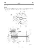
Note: Apply THREE-BOND 1104 to the following 5 places: mating face of the gear case (18) and the gear case
cover (37); mating face of the gear case (18) and the bracket (1); mating face of the gear case (18) and the
bearing retainer (7); mating face of the gear case (18) and the bearing retainer (21); mating face of the gear case
(18) and the bearing retainer (22). When installing the oil seals (5) and (23), apply THREE-BOND 1215 to their
external periphery and inject lithium based grease to their internal periphery. Apply NEVER-SEEZ to the
following 2 places: toothed mating face of the drum shaft (30) and the drum boss (27); cylindrical mating face of
the drum shaft (30) and the drum (29). The amount of the gear oil is approx. 1.1 gal. (4 L). Do not disassemble
the sleeve (41).
1.Bracket
3.Bolt
4.Spring washer
5.Oil seal
7.Bearing retainer
8.Ball bearing
9.Nut
10.Washer
11.Collar
12.Bolt
13.Spring washer
14.Drum gear
15.Collar
16.Ball bearing
17.Ball bearing
18.Gear case
19.Spur gear
20.Ball bearing
21.Bearing retainer
22.Bearing retainer
23.Oil seal
24.Bolt
25.Spring washer
26.Lock plate
27.Drum boss
28.Pin
29.Drum
30.Drum shaft
31.Ball bearing
32.Bearing stand
33.Bolt
34.Spring washer
35.Plug
36.Elbow joint
37.Gear case cover
38.Plug
41.Sleeve
Thread size and tightening torque
Tightening torque
Sign / port
Thread size
N-m ft-lbf
3 *1
M14
177 - 190
130 - 140
12
M12
69 - 82
51 - 61
24
M20
353 - 392
260 - 289
33
M8
32 - 34
24 - 25
35 *2
R3/4
106 - 132
78 - 98
38 *3
R3/8
44 - 62
33 - 46
Mounting bolt
M20
431 - 471
318 - 347
*1: Apply THREE-BOND 1305 to threaded sections.
*2: Oil filler port.
*3: Oil level port on the top and drain port on the bottom.
△
0
360-730-30000
△
0
360-731-80000
Summary of Contents for TR-800XXL4
Page 47: ...B 9 B 9 Rotary Joint 27 W181 0440E Upper view A Lower view B...
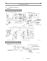
Page 119: ...F 1 F 1 Winch System 1 WF02 0251E F 1 Winch System 1 General Hydraulic Circuit for Winch...
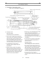
Page 135: ...G 1 G 1 Telescoping System 3 WG02 0321E Telescoping cylinder at select...
Page 143: ...G 2 G 2 Boom Five Section Boom G 2 11 W536 0761E 11...
Page 196: ...13 13 W701 0220E K 2 K 2 Air Conditioner K 2 4 Layout 4 1 Overall layout 4 345 107 61000...
Page 197: ...14 14 W701 0220E K 2 K 2 Air Conditioner K 2 4 2 Overall layout 0 345 110 73000...
Page 198: ...15 15 W701 0220E K 2 K 2 Air Conditioner K 2 4 3 Evaporator section 5 345 107 02000...
Page 199: ...16 W701 0220E K 2 K 2 Air Conditioner 5 Compressor Assy...
Page 200: ...17 17 W701 0220E K 2 K 2 Air Conditioner K 2 6 Evaporator Assy...
Page 201: ...18 18 W701 0220E K 2 K 2 Air Conditioner K 2 7 Condenser Assy...
Page 202: ...19 19 W701 0220E K 2 K 2 Air Conditioner K 2 8 Electric 8 1 Electric circuit 0 363 205 60030...
Page 203: ...20 20 W701 0220E K 2 K 2 Air Conditioner K 2 8 2 Main harness A...
Page 204: ...21 21 W701 0220E K 2 K 2 Air Conditioner K 2 8 3 Main harness B...
Page 222: ...39 K 2 K 2 K 2 Air Conditioner 39 W701 0220E 12 2Compressor diagnosis chart 1 2...
Page 223: ...40 K 2 K 2 K 2 Air Conditioner 40 W701 0220E Compressor diagnosis chart 2 2...
Page 224: ...K 2 K 2 Air Conditioner 41 W701 0220E 13 Troubleshooting...
Page 225: ...K 2 K 2 Air Conditioner 42 W701 0220E...
Page 226: ...K 2 K 2 Air Conditioner 43 W701 0220E...
Page 227: ...K 2 K 2 Air Conditioner 44 W701 0220E...
Page 228: ...K 2 K 2 Air Conditioner 45 W701 0220E...
Page 229: ...K 2 K 2 Air Conditioner 46 W701 0220E...
Page 237: ...L 1 L 1 Control System 2 WL02 0090E 2 General of pneumatic control devices Pneumatic Circuit...
Page 291: ...T 5 T 5 Air Dryer 26 W232 0032E Heater View A 39 C B B A 58 59 2 IW232 0030E03...
Page 370: ...8 8 WZ03 3300E Z 5 Z 5 Electric Circuit MDT Carrier Upper Z 5 IWZ03 3300E01...
Page 372: ...10 Z 6 Z 6 Electric Circuit MDT Carrier Lower Z 6 10 WZ03 3310E IWZ03 3310E01...
Page 400: ...38 Z 24 Z 24 Harness Lower Sub 38 WZ04 2450E Z 24 Z 24 Harness Lower Sub 2 349 310 00200...


