


Y - 3
Y - 3
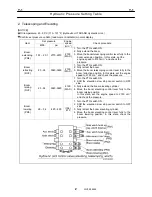
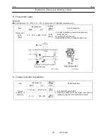
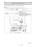
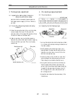
Air Bleeding Procedure
11
WY05-0581E
Y-3
Air Bleeding Procedure
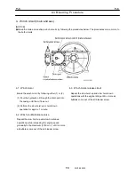
1. Starting pump
1.1 Before starting the engine
Make sure that
• PTO switch is turned OFF.
• The oil cooler is not functioning (due to the
hydraulic oil temperature below 50°C (122°F)).
1.2 Shakedown of the pump
1) Steering, winch brake pilot pressure pump
(double gear pumps)
1. Fill the oil tank with hydraulic oil.
2. With the engine stopped, loosen the air-bleed plug
on the suction flange of the main pump. After
bleeding air from the suction side, tighten the plug
again.
3. Start the engine (with PTO OFF) and run it at idle
(approx. 700 min
-1
) while bleeding the air from the
circuit for 1 minute.
4. Start the engine, and run-in the engine for 10
minutes at idle.
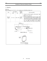
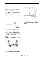
2) Main pump
1. Fill the oil tank with hydraulic oil. (If the suction
section was disassembled for repair or other
reasons, bleed air from the air-bleed plug on the
suction side, as described above.)
[NOTICE]
If the tank is to be pressurized, pressurize it at a
pressure of 15 kPa {2.2 psi} or less.
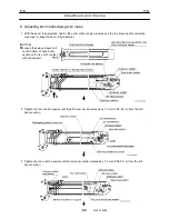
2. Bleed the air from the pump case. Remove the
drain plug or drain hose from the pump. Inject oil
into this location until it overflows, then reinsert
the plug.
3. Start the engine, with PTO ON, and run-in the
engine at idle for 5 minutes.
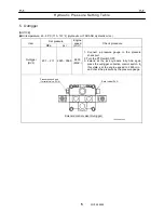
3) Others
• After the shakedown of the pump, do not let the
engine speed exceed the middle range (1000
min
-1
) if you bleed the cylinders.
When you try to raise the oil temperatuer in
order to adjust the hydraulic pressure, make
sure that there is no bubbles caused by the
bleeding in the tank.
Summary of Contents for TR-800XXL4
Page 47: ...B 9 B 9 Rotary Joint 27 W181 0440E Upper view A Lower view B...
Page 119: ...F 1 F 1 Winch System 1 WF02 0251E F 1 Winch System 1 General Hydraulic Circuit for Winch...
Page 135: ...G 1 G 1 Telescoping System 3 WG02 0321E Telescoping cylinder at select...
Page 143: ...G 2 G 2 Boom Five Section Boom G 2 11 W536 0761E 11...
Page 196: ...13 13 W701 0220E K 2 K 2 Air Conditioner K 2 4 Layout 4 1 Overall layout 4 345 107 61000...
Page 197: ...14 14 W701 0220E K 2 K 2 Air Conditioner K 2 4 2 Overall layout 0 345 110 73000...
Page 198: ...15 15 W701 0220E K 2 K 2 Air Conditioner K 2 4 3 Evaporator section 5 345 107 02000...
Page 199: ...16 W701 0220E K 2 K 2 Air Conditioner 5 Compressor Assy...
Page 200: ...17 17 W701 0220E K 2 K 2 Air Conditioner K 2 6 Evaporator Assy...
Page 201: ...18 18 W701 0220E K 2 K 2 Air Conditioner K 2 7 Condenser Assy...
Page 202: ...19 19 W701 0220E K 2 K 2 Air Conditioner K 2 8 Electric 8 1 Electric circuit 0 363 205 60030...
Page 203: ...20 20 W701 0220E K 2 K 2 Air Conditioner K 2 8 2 Main harness A...
Page 204: ...21 21 W701 0220E K 2 K 2 Air Conditioner K 2 8 3 Main harness B...
Page 222: ...39 K 2 K 2 K 2 Air Conditioner 39 W701 0220E 12 2Compressor diagnosis chart 1 2...
Page 223: ...40 K 2 K 2 K 2 Air Conditioner 40 W701 0220E Compressor diagnosis chart 2 2...
Page 224: ...K 2 K 2 Air Conditioner 41 W701 0220E 13 Troubleshooting...
Page 225: ...K 2 K 2 Air Conditioner 42 W701 0220E...
Page 226: ...K 2 K 2 Air Conditioner 43 W701 0220E...
Page 227: ...K 2 K 2 Air Conditioner 44 W701 0220E...
Page 228: ...K 2 K 2 Air Conditioner 45 W701 0220E...
Page 229: ...K 2 K 2 Air Conditioner 46 W701 0220E...
Page 237: ...L 1 L 1 Control System 2 WL02 0090E 2 General of pneumatic control devices Pneumatic Circuit...
Page 291: ...T 5 T 5 Air Dryer 26 W232 0032E Heater View A 39 C B B A 58 59 2 IW232 0030E03...
Page 370: ...8 8 WZ03 3300E Z 5 Z 5 Electric Circuit MDT Carrier Upper Z 5 IWZ03 3300E01...
Page 372: ...10 Z 6 Z 6 Electric Circuit MDT Carrier Lower Z 6 10 WZ03 3310E IWZ03 3310E01...
Page 400: ...38 Z 24 Z 24 Harness Lower Sub 38 WZ04 2450E Z 24 Z 24 Harness Lower Sub 2 349 310 00200...


