


33
W181-0440E
B - 9 .
B - 9 .
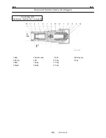
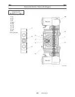
Rotary Joint
2. Potentiometer
2.1 Adjustment
1. Install the potentiometer as shown in the figure
below. However, tighten the bolt for fixing the lever
lightly. (Do not fix the lever to the potentiometer
shaft because you must turn the potentiometer
shaft using the slotted screwdriver to adjust the
position of the shaft.)
IW181-0260E12
Hexagon socket head bolt
Potentiometer
Slotted screwdriver
Lever
Bolt (Tighten lightly.)
2. While keeping the stamp mark on the guide
oriented as shown in the figure below, adjust the
potentiometer as described in the following steps.
(If you adjust the potentiometer with the slip ring
assy installed on the crane, direct the boom
over-left to orient the stamp mark as shown in the
figure below.)
Guide
IW181-0260E13
Stamp mark
Slip ring assy
3. Turn the potentiometer shaft using a slotted
screwdriver so that the resistance between the
upper terminals 1 and 2 is minimum between 1
ohm and 15 ohm. Leave the terminals (6 pieces)
of the potentiometer disconnected.
IW181-0260E14
Potentiometer
Slotted screwdriver
Lower terminals 1, 2 and 3
Terminal 1
Upper terminals 1, 2 and 3
Terminal 2
Terminal 3
3
2
1
4. Remove the hexagon socket head bolts (4 pieces),
take out the potentiometer and fully tighten the
bolt for fixing the lever. Then install the
potentiometer and make sure that the resistance
between the upper terminals 1 and 2 is 15 ohm or
less.
2.2 Soldering
1. After finishing the potentiometer adjustment,
remove the hexagon socket head bolts (4 pieces)
and take out the potentiometer. Then solder the
wiring to the terminals (6 pieces).
2. To insulate the terminals (6 pieces) from one
another, coat the terminal section with epoxy
adhesive (equivalent to 3M DP-420).
△
7
346-305-71000
Summary of Contents for TR-800XXL4
Page 47: ...B 9 B 9 Rotary Joint 27 W181 0440E Upper view A Lower view B...
Page 119: ...F 1 F 1 Winch System 1 WF02 0251E F 1 Winch System 1 General Hydraulic Circuit for Winch...
Page 135: ...G 1 G 1 Telescoping System 3 WG02 0321E Telescoping cylinder at select...
Page 143: ...G 2 G 2 Boom Five Section Boom G 2 11 W536 0761E 11...
Page 196: ...13 13 W701 0220E K 2 K 2 Air Conditioner K 2 4 Layout 4 1 Overall layout 4 345 107 61000...
Page 197: ...14 14 W701 0220E K 2 K 2 Air Conditioner K 2 4 2 Overall layout 0 345 110 73000...
Page 198: ...15 15 W701 0220E K 2 K 2 Air Conditioner K 2 4 3 Evaporator section 5 345 107 02000...
Page 199: ...16 W701 0220E K 2 K 2 Air Conditioner 5 Compressor Assy...
Page 200: ...17 17 W701 0220E K 2 K 2 Air Conditioner K 2 6 Evaporator Assy...
Page 201: ...18 18 W701 0220E K 2 K 2 Air Conditioner K 2 7 Condenser Assy...
Page 202: ...19 19 W701 0220E K 2 K 2 Air Conditioner K 2 8 Electric 8 1 Electric circuit 0 363 205 60030...
Page 203: ...20 20 W701 0220E K 2 K 2 Air Conditioner K 2 8 2 Main harness A...
Page 204: ...21 21 W701 0220E K 2 K 2 Air Conditioner K 2 8 3 Main harness B...
Page 222: ...39 K 2 K 2 K 2 Air Conditioner 39 W701 0220E 12 2Compressor diagnosis chart 1 2...
Page 223: ...40 K 2 K 2 K 2 Air Conditioner 40 W701 0220E Compressor diagnosis chart 2 2...
Page 224: ...K 2 K 2 Air Conditioner 41 W701 0220E 13 Troubleshooting...
Page 225: ...K 2 K 2 Air Conditioner 42 W701 0220E...
Page 226: ...K 2 K 2 Air Conditioner 43 W701 0220E...
Page 227: ...K 2 K 2 Air Conditioner 44 W701 0220E...
Page 228: ...K 2 K 2 Air Conditioner 45 W701 0220E...
Page 229: ...K 2 K 2 Air Conditioner 46 W701 0220E...
Page 237: ...L 1 L 1 Control System 2 WL02 0090E 2 General of pneumatic control devices Pneumatic Circuit...
Page 291: ...T 5 T 5 Air Dryer 26 W232 0032E Heater View A 39 C B B A 58 59 2 IW232 0030E03...
Page 370: ...8 8 WZ03 3300E Z 5 Z 5 Electric Circuit MDT Carrier Upper Z 5 IWZ03 3300E01...
Page 372: ...10 Z 6 Z 6 Electric Circuit MDT Carrier Lower Z 6 10 WZ03 3310E IWZ03 3310E01...
Page 400: ...38 Z 24 Z 24 Harness Lower Sub 38 WZ04 2450E Z 24 Z 24 Harness Lower Sub 2 349 310 00200...


