17
W536-0761E
G - 2
G - 2
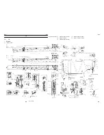
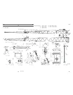
Boom (Five-Section Boom)
3. Check
3.1 Boom
Check the boom for twist, deformation, wrap, and
cracks.
3.2 Slide plate
Check the slide plates for cracks and wear, and
replace when these conditions are excessive.
3.3 Sheave
Check the sheaves for damage, deformation and
wear, and replace them when these conditions are
excessive.
3.4 Boom telescoping wire rope
Wire rope in the condition described below must not
be used.
• Deformation or corrosion
• Kinking
• 10% or more broken wire (filler wires excluded) in
one lay of the wire rope
• diameter reduction exceeding 7% of the nominal
diameter.
• Evidence of any heat damage from any cause.
4. Reassembly
4.1 Greasing
• When installing unplated pins, apply grease
beforehand.
• Apply TNR-2 Grease sufficienty to the sliding
surfaces of the slide plates, the booms and
telescoping cylinders.
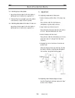
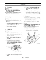
4.2 Install anti-buckling bolts for telescoping
cylinder
IW536-0680E12
E
D
S
C
A
B
Boom side
Cylinder side
1. Connect the boom and telescoping cylinder using
the pins A and B.
2. Adjust the bolt C locked with nuts D and E so that
it can be turned by hand and the clearance (S) is
0.5mm (0.02in) or less.(Apply thread locking
agent.)
[NITICE]
Refer to normal insert directions of bolt•C shown on
[2.Disassembly]
Base and 2nd boom section
3rd boom section
Summary of Contents for TR-800XXL4
Page 47: ...B 9 B 9 Rotary Joint 27 W181 0440E Upper view A Lower view B...
Page 119: ...F 1 F 1 Winch System 1 WF02 0251E F 1 Winch System 1 General Hydraulic Circuit for Winch...
Page 135: ...G 1 G 1 Telescoping System 3 WG02 0321E Telescoping cylinder at select...
Page 143: ...G 2 G 2 Boom Five Section Boom G 2 11 W536 0761E 11...
Page 196: ...13 13 W701 0220E K 2 K 2 Air Conditioner K 2 4 Layout 4 1 Overall layout 4 345 107 61000...
Page 197: ...14 14 W701 0220E K 2 K 2 Air Conditioner K 2 4 2 Overall layout 0 345 110 73000...
Page 198: ...15 15 W701 0220E K 2 K 2 Air Conditioner K 2 4 3 Evaporator section 5 345 107 02000...
Page 199: ...16 W701 0220E K 2 K 2 Air Conditioner 5 Compressor Assy...
Page 200: ...17 17 W701 0220E K 2 K 2 Air Conditioner K 2 6 Evaporator Assy...
Page 201: ...18 18 W701 0220E K 2 K 2 Air Conditioner K 2 7 Condenser Assy...
Page 202: ...19 19 W701 0220E K 2 K 2 Air Conditioner K 2 8 Electric 8 1 Electric circuit 0 363 205 60030...
Page 203: ...20 20 W701 0220E K 2 K 2 Air Conditioner K 2 8 2 Main harness A...
Page 204: ...21 21 W701 0220E K 2 K 2 Air Conditioner K 2 8 3 Main harness B...
Page 222: ...39 K 2 K 2 K 2 Air Conditioner 39 W701 0220E 12 2Compressor diagnosis chart 1 2...
Page 223: ...40 K 2 K 2 K 2 Air Conditioner 40 W701 0220E Compressor diagnosis chart 2 2...
Page 224: ...K 2 K 2 Air Conditioner 41 W701 0220E 13 Troubleshooting...
Page 225: ...K 2 K 2 Air Conditioner 42 W701 0220E...
Page 226: ...K 2 K 2 Air Conditioner 43 W701 0220E...
Page 227: ...K 2 K 2 Air Conditioner 44 W701 0220E...
Page 228: ...K 2 K 2 Air Conditioner 45 W701 0220E...
Page 229: ...K 2 K 2 Air Conditioner 46 W701 0220E...
Page 237: ...L 1 L 1 Control System 2 WL02 0090E 2 General of pneumatic control devices Pneumatic Circuit...
Page 291: ...T 5 T 5 Air Dryer 26 W232 0032E Heater View A 39 C B B A 58 59 2 IW232 0030E03...
Page 370: ...8 8 WZ03 3300E Z 5 Z 5 Electric Circuit MDT Carrier Upper Z 5 IWZ03 3300E01...
Page 372: ...10 Z 6 Z 6 Electric Circuit MDT Carrier Lower Z 6 10 WZ03 3310E IWZ03 3310E01...
Page 400: ...38 Z 24 Z 24 Harness Lower Sub 38 WZ04 2450E Z 24 Z 24 Harness Lower Sub 2 349 310 00200...


