


K - 2
K - 2
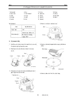
Air Conditioner
7
W701-0220E
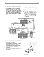
3.3 Refrigerant
1. The substance that circulates through the
refrigeration cycle, and functions to transmit heat,
is known as the refrigerant. In our air conditioning
system, HFC134a is used. It is a freon-based
refrigerant, but does not contain chlorine.
2. As shown in the figure below, the refrigerant
HFC134a remains in liquid form at relatively high
temperatures when it is strongly compressed.
However, at low pressures it vaporizes at
temperatures as low as 0°C (32°F) or
-10°C (14°F).
3. This means, for example, that if the refrigerant
vaporizes at 0°C (32°F), then the evaporator is
also at 0°C (32°F). The air that passes through
this evaporator should be cooled.
4. If the pressure is reduced so that the refrigerant
evaporates at -5°C (23°F), the evaporator is also
maintained at -5°C (23°F). This results in the
formation of frost, which inhibits the flow of air
through the evaporator and prevents cooling.
5. The vaporized refrigerant must then be liquefied.
However, it is impossible to obtain a temperature
as low as 40°C (104°F) in a hot summer
environment.
6. If 60
°
C (140°F) is possible, HFC134a will become
a liquid at 60°C (140°F) if the pressure is
approximately 1.7 MPa (246.5 psi) or above.
When the gaseous refrigerant is compressed to
1.7 MPa (246.5 psi) (by the compressor), the gas
temperature rises to approximately 80°C (176°F).
7. Therefore, the temperature of the gas as it enters
the condenser is 80°C (176°F). The curve above
shows that when the refrigerant gas is cooled by
20°C (68°F), it becomes a liquid at approximately
60°C (140°F) by the time it reaches the condenser
outlet.
Summary of Contents for TR-800XXL4
Page 47: ...B 9 B 9 Rotary Joint 27 W181 0440E Upper view A Lower view B...
Page 119: ...F 1 F 1 Winch System 1 WF02 0251E F 1 Winch System 1 General Hydraulic Circuit for Winch...
Page 135: ...G 1 G 1 Telescoping System 3 WG02 0321E Telescoping cylinder at select...
Page 143: ...G 2 G 2 Boom Five Section Boom G 2 11 W536 0761E 11...
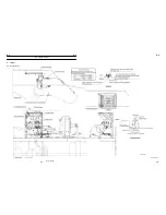
Page 196: ...13 13 W701 0220E K 2 K 2 Air Conditioner K 2 4 Layout 4 1 Overall layout 4 345 107 61000...
Page 197: ...14 14 W701 0220E K 2 K 2 Air Conditioner K 2 4 2 Overall layout 0 345 110 73000...
Page 198: ...15 15 W701 0220E K 2 K 2 Air Conditioner K 2 4 3 Evaporator section 5 345 107 02000...
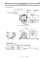
Page 199: ...16 W701 0220E K 2 K 2 Air Conditioner 5 Compressor Assy...
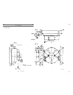
Page 200: ...17 17 W701 0220E K 2 K 2 Air Conditioner K 2 6 Evaporator Assy...
Page 201: ...18 18 W701 0220E K 2 K 2 Air Conditioner K 2 7 Condenser Assy...
Page 202: ...19 19 W701 0220E K 2 K 2 Air Conditioner K 2 8 Electric 8 1 Electric circuit 0 363 205 60030...
Page 203: ...20 20 W701 0220E K 2 K 2 Air Conditioner K 2 8 2 Main harness A...
Page 204: ...21 21 W701 0220E K 2 K 2 Air Conditioner K 2 8 3 Main harness B...
Page 222: ...39 K 2 K 2 K 2 Air Conditioner 39 W701 0220E 12 2Compressor diagnosis chart 1 2...
Page 223: ...40 K 2 K 2 K 2 Air Conditioner 40 W701 0220E Compressor diagnosis chart 2 2...
Page 224: ...K 2 K 2 Air Conditioner 41 W701 0220E 13 Troubleshooting...
Page 225: ...K 2 K 2 Air Conditioner 42 W701 0220E...
Page 226: ...K 2 K 2 Air Conditioner 43 W701 0220E...
Page 227: ...K 2 K 2 Air Conditioner 44 W701 0220E...
Page 228: ...K 2 K 2 Air Conditioner 45 W701 0220E...
Page 229: ...K 2 K 2 Air Conditioner 46 W701 0220E...
Page 237: ...L 1 L 1 Control System 2 WL02 0090E 2 General of pneumatic control devices Pneumatic Circuit...
Page 291: ...T 5 T 5 Air Dryer 26 W232 0032E Heater View A 39 C B B A 58 59 2 IW232 0030E03...
Page 370: ...8 8 WZ03 3300E Z 5 Z 5 Electric Circuit MDT Carrier Upper Z 5 IWZ03 3300E01...
Page 372: ...10 Z 6 Z 6 Electric Circuit MDT Carrier Lower Z 6 10 WZ03 3310E IWZ03 3310E01...
Page 400: ...38 Z 24 Z 24 Harness Lower Sub 38 WZ04 2450E Z 24 Z 24 Harness Lower Sub 2 349 310 00200...


