


76
TROUBLESHOOTING
Shot Timers are Cycling Through All Possible Indicators:
•
Shot timer is stuck in test mode. Check that the jumper is seated on the shot timer board pins. If jumper
is in place and test mode continues, replace the shot timer board.
Heating Elements
WARNING: High voltage may be present. Disconnect machine from power supply before testing.
•
Test with an ohm meter across the element posts (steam element has two loops; upper and lower). See
heating element specs table. If reading is out of spec, the element has failed.
•
Testing the element post to the element body or to the frame (ground) should not give a continuity read-
ing of any kind. If you get even a quick flash reading, remove element and inspect.
Valve Solenoids and Solenoid Switches
WARNING: High voltage may be present. Risk of electric shock. Testing should be performed by a qualified
technician only. Extreme caution should be used.
Valve is NOT Opening:
•
When the valve is signaled to open, a red light should be lit on the solenoid switch. If the valve should be
receiving a signal to open and a red light is not present, the low voltage signal or ground may be inter-
rupted. Further electrical troubleshooting is required.
•
If a red light is present on the solenoid switch when the valve is signaled to open, check for 220 VAC
across the red and blue wires to ensure the solenoid is being powered. If 220 VAC is present, replace the
valve and solenoid. If 220 VAC is not present, further electrical troubleshooting is required.
Steam Wand
Drip at the Steam Wand Tip:
•
A small amount of water will naturally drip as water condenses and accumulates in the wand between
uses. Make a habit of purging the steam wand of all accumulated liquids before and directly after steam-
ing a pitcher of milk.
•
Steam valve seal is worn. Replace by installing steam valve rebuilt kit.
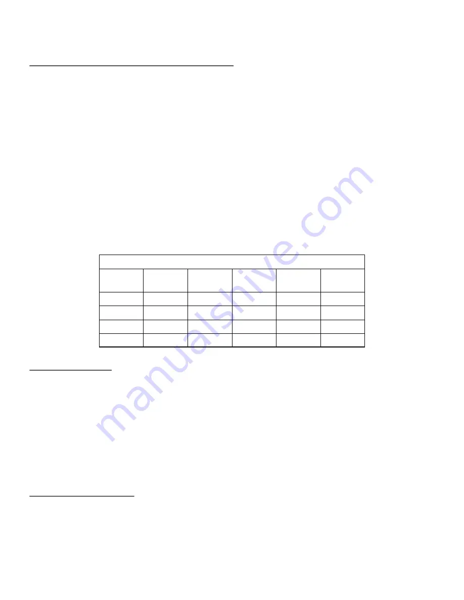
Heating Element Specs
Tank
Groups/
model
Watts
Amp 208
VAC
Amp 240
VAC
Ohm range
Steam
3
5000
24
20
18
-
22
Steam
2
4000
19.2
16.7
22
-
26
Steam
1
2000
9.6
8.3
46
-
52
Brew
all
700
3.4
2.9
64
-
72
Summary of Contents for MVP
Page 12: ...12 INSTALLATION DIMENSIONS ...
Page 26: ...26 HYDRAULIC SCHEMATIC MVP ...
Page 27: ...27 HYDRAULIC SCHEMATIC MVP HYDRA ...
Page 34: ...34 ELECTRICAL SYSTEM Main Electronics Board MVP MVP Hydra ...
Page 38: ...38 ELECTRICAL SYSTEM Electrical Schematic ...
Page 44: ...44 PROGRAMMING Brew System Error Codes ...
Page 45: ...45 PROGRAMMING Brew System Error Codes ...
Page 46: ...46 PROGRAMMING Brew System Error Codes ...
Page 48: ...48 PROGRAMMING Steam System Error Codes ...
Page 49: ...49 PROGRAMMING Steam System Error Codes ...
Page 50: ...50 PROGRAMMING Steam System Error Codes ...
Page 71: ...71 TEMPERATURE OFFSETS ...


