Svantek SVAN 106 User Manual Download Page 60

SVAN 106 User MANUAL                                                                                                                    

                                                                                                         _ 

60 

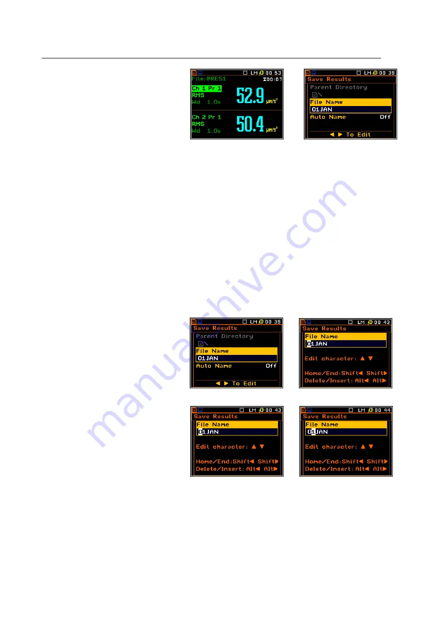
There are two options for storing result data 
in  the  internal  or  external  memory.  One 
option is to press <Save> push-button right 
after 

the 

measurement 

performance. 

Another  option  is  to  create  <New File>  in 
the File Manager.  

After  pressing  the  <Save>  push-button  the 
Save Results window appears.  


<Save>


There  are  two  available  options  for  saving  files:  with  the  edited  name,  or  with  the  name  automatically 
changed  with  the  name  increased  by  one.  These  options  can  be  selected  in  the  position  Auto Name.  If 
Auto Name is switched off (Off) the name of the saved file is like in the position File Name. This file name 
can be edited in the special window, which is opening by means of <

4

4

4

4

> push-button. When the Auto Name 

function  is  set  on  Number,  then  a  file  is  saved  with  the  name  as  displayed  above,  but  after  the  last  non-
numeric letter of the text there will be added digit 0. If there already exists any chain of digits on the end of 
the file text the number that these digits create will be increased by one.  

The  number  can  be  changed  from  0  to  N. The  only  limitation  of  the  N  value  is  the  length  of  the  file  name, 
which  cannot  be  longer  than  eight  characters.  In  the  case,  when  such  limitation  is  achieved  and  the 
instrument can not change automatically the file’s name the only possibility is to edit new file name.  

The default name for a file is displayed in the case of the first entering to this position (after power on). The 
default name consists of the day and the month’s abbreviation and cannot exceed 8 characters.  

The user can skip the file’s name edition and start saving file pressing the <ENTER> push-button or return to 
the File list or measurement display by pressing the <ESC> one.  

To  start file  edition  the  user  has  to  select 
the  File name  position  and  to  press  <

3

3

3

3

> 

or <

4

4

4

4

push-button. After that the special 

window  with  edition  function  is  opening. 
The  edition  process  is  presented  on  the 
Figure below. 


 <

4

4

4

4


Selection of the character’s position to 
be edited 

One  can  select  the  position  of  the 
character  in  the  edited  text  using  the 
<

3

3

3

3

>,  <

4

4

4

4

>  push-buttons.  For  the  current 

position  the  character  can  be  changed, 
position can be deleted or inserted. 


 <

4

4

4

4


Summary of Contents for SVAN 106

Page 1: ...SVAN 106 User MANUAL _ 1 SVAN Vibration Meter USER S MANUAL SVANTEK Sp z o o WARSAW August 2012...

Page 2: ...ents the software revision named 3 13 1 cf the description of the Unit Label position of the Instrument list The succeeding software revisions marked with the bigger numbers can slightly change the vi...

Page 3: ...sducer s sensitivity Calibr By Sensitivity 23 4 3 4 Calibration by measurement Calibr By Measurement 23 4 3 5 History of the calibrations Calibration History 25 4 3 6 Clear calibration records Clear C...

Page 4: ...ting new catalogue and new file 64 7 2 3 Deleting all files from Internal memory Delete All 64 7 2 4 Merging result and setup files memory Defragmentation 65 7 2 5 Opening file catalogue Open 66 7 2 6...

Page 5: ...meters of 1 1 Octave and 1 3 Octave analysis 83 10 3 Activation of saving of 1 1 Octave and 1 3 Octave analysis results in the logger s file Logger Results 84 10 4 Selection of the 1 1 Octave and 1 3...

Page 6: ...itionally for measurements of very high impulse vibration the special adapter SA 55 with low pass mechanical filter protecting accelerometer from DC shift effect is available Evaluation of the grip fo...

Page 7: ...SB 1 1 cable typical 2m SC 118 LEMO 4 pin to LEMO 5 pin connector SV 38V triaxal accelerometer for Whole Body measurements MEMS type SV 105 integrated triaxal Hand Arm adapter with grip force sensor u...

Page 8: ...the Alt push button Shift The second function of a push button written in red colour on a push button can be used when the Shift push button is pressed This push button can be used in two different w...

Page 9: ...er access to the frequently used sub lists Save This push button pressed together with the Alt one enables the user to save measurement results as a file in the internal instrument s memory or on the...

Page 10: ...ode of result s presentation programme the Real Clock RTC and Timer Info The Info push button simultaneous pressing the 3 3 3 3 4 4 4 4 push buttons opens the window with the help information in the m...

Page 11: ...plot with markers the user has to transfer data to the proper software 20 30 40 50 60 70 80 13 30 00 13 30 09 13 30 17 13 30 26 13 30 35 13 30 43 13 30 52 Leq Marker 1 Marker 2 Marker 3 Marker 4 2 2 I...

Page 12: ...additional multi purpose input output socket called I O is a two pins LEMO socket On this socket in the case when the Analogue Output functionality is selected the signal from the input of the analogu...

Page 13: ...nd list Main menu The main list contains the headers of six lists which also contain sub lists or positions The main list is opened after pressing the Menu push button This list contains the following...

Page 14: ...of different options from which the only one may be selected The selection of the option is performed next way The user has to highlight the desired option by means of 5 5 5 5 or 6 6 6 6 push buttons...

Page 15: ...der for the printed reports from the measurements This window consists the help information to guide the user how to edit the text The displayed inversely character may be edited One can select the po...

Page 16: ...g sources Four AA standard internal batteries In the case of alkaline type fully charged set can operate more than 12 h 6 0 V 1 6 Ah Instead of the ordinary four AA rechargeable batteries can be used...

Page 17: ...s the Alt and Start Stop push buttons in parallel The instrument passes the self test after switching on in this time the producer and the name of the instrument is displayed on the display and then i...

Page 18: ...n the top of the display The type of measurement function and the measurement mode LM DLM 1 1 and 1 3 etc as well as RTC is also displayed in the same line together with icons The meanings of the icon...

Page 19: ...s Icon corresponds to the batteries state three two one or none vertical bars in side of the icon When voltage of batteries is too low the icon became red Shift icon is displayed when the Shift push b...

Page 20: ...press the ENTER push button After the new window is opening one should select the Set Working Directory position and press the ENTER push button again The icon on the upper line and the directory pat...

Page 21: ...functions In all functions it is possible to perform additionally dose measurements Dose parameters are setting up in HAV WBV Dose window path Menu Measurement In order to select the required function...

Page 22: ...ition enables the user to Download TEDS Data when accelerometer is connected during instrument s working session It enables also to Upload TEDS Data from the instrument to the accelerometer s TEDS mem...

Page 23: ...sitivity of the accelerometer taken from its calibration certificate using the 3 3 3 3 4 4 4 4 push buttons or combination of the Shift and 3 3 3 3 4 4 4 4 push buttons The calibration factor is calcu...

Page 24: ...nt time is also predefined to 5 seconds During the calibration period the ESC and Pause push buttons do not operate but it is possible to stop the measurement using the Start Stop push button Waiting...

Page 25: ...calibration record the user has to use the 5 5 5 5 6 6 6 6 push buttons The opened window contains the date and time of the performed calibration measurement the way the calibration was done Calibr By...

Page 26: ...in the Calibration sub list and press ENTER The instrument requests the confirmation of the operation The next pressing of the ENTER push button when the No option is selected causes the closing of th...

Page 27: ...he Measurement menu can be changed only when the instrument does not execute a measurement The parameters are displayed with different colour and any marker movement is impossible The blinking play ic...

Page 28: ...in the range of from 1 s to 59 s with 1 second or 10 seconds step from 1 m min to 59 m with 1 minute or 10 minutes step from 1 h to 24 h with 1 hour or 10 hours step It is also possible to set Inf val...

Page 29: ...easurement ENT Dosimeter parameters can be setup in the HAV WBV Dosimeter window opened from the Measurement list If the Dosimeter function is switched on then the HAV WBV Dosimeter position in the Me...

Page 30: ...etup Instrument Mode If the Event Recording function is switched off then the Event Recording position in the Data Logging list will be not active 5 2 Setting the parameters for dose measurements HAV...

Page 31: ...dose measurements The Standard position enables the user to set the standards for the measurements of the HAV WBV Dosimeter The available values of this position are U K Italy Poland France Germany a...

Page 32: ...channels will be disabled and will not be displayed Activation of second profiles In the Enabled 2nd profiles the user may switch on or off result calculations for the second profiles If second profil...

Page 33: ...always available filter HP Second available filter for profile 2 is one of BL Wh BL Wk BL Wd BL Wc BL Wj BL Wm BL Wg BL Wb and BL Wf according to the rule if Wh filter is selected in the profile 1 th...

Page 34: ...lculate vector with other than standard coefficients it is possible to select the coefficient within the values from 0 00 to 2 00 The values presented above are taken into account during the calculati...

Page 35: ...nnels and Wave Trigger 5 6 The results history logging When Logger function is chosen for the Logging Mode the Data Logging list enables one to program saving the history of results in the logger file...

Page 36: ...tion of the user any push button should be pressed except the Shift or the Alt one The main measurement results cf App B are calculated in the period set on in the Meas Period These results can be sav...

Page 37: ...od from N 1 T to NT sig1 svn sig2 svn sigN 1 svn sigN svn time time history PEAK MAX MIN or RMS LOGGER STEP 0 NT LOGGER ON RMS results logged with LOGGER STEP Number of results equal NT LS logger1 svn...

Page 38: ...s with names Channels x y Channels x y Profile z Channel x Channel x Profile y The VDV history will not be recorded if Wh filer is chosen in this profile Activation deactivation can be done by means o...

Page 39: ...Measurement Data Logging Logger Setup all measurement results up to the moment the triggering condition disappears the results registered directly after the moment the triggering condition disappears...

Page 40: ...iggering condition is not fulfilled Step for checking the triggering condition The Trig Step position enables one to select integration time for condition evaluation Logger step 100ms 1 0s Meas Time a...

Page 41: ...position is selected then event recording will start by trigger Trigger condition is set up in the window opened by position Trigger Parameters This position appears in the list after activation the T...

Page 42: ...d When Max Length is chosen then the signal will be recording during period defined in the Rec Time but can be stopped earlier if trigger condition was ceased When Fixed Len is chosen then the signal...

Page 43: ...tive It only informs about the used type of wave recording Continuous The user may define the format of the wave file header Format Format of the wave file header may be PCM or Extensible The Sampling...

Page 44: ...next triggering condition appears then the signal will be recording additional Rec Time 4 4 4 4 The position Trigger Parameters enables to define the parameters of the triggering signal To open this...

Page 45: ...control code remotely The next sources of the triggering signal are available RMS 1 VEC46 VEC13 or External External source means that the triggering will take place from the positive or negative slop...

Page 46: ...ion path Menu Display Results Scale Setting the speed of the triggering signal changes This position appears when the Gradient or Gradient trigger is chosen The speed of the triggering signal changes...

Page 47: ...ut ENT The Alarm Trigger window and meaning of all positions is identical as for Logger Trigger case 5 11 Programming the instrument s internal timer Timer The Timer position appears only in Advanced...

Page 48: ...mer can be programmed up to one month ahead and during the date setting the current state of the Real Clock is taken into account The required date can be selected in the special window which is opene...

Page 49: ...SVAN 106 User MANUAL _ 49...

Page 50: ...presentation Results Scale enables one to change the scale of result s presentation Screen enables one to set the brightness and the switch on off the screen saver of the instrument s display 6 1 Sel...

Page 51: ...ode 6 Channels presentation mode 6 Profiles presentation mode When all display modes in the Display Modes list are switched on they all are available and can be selected by means of Alt and 5 5 5 5 6...

Page 52: ...shows the current second of the measurement The value presented there belongs to the range 1 Meas Period 5 The value of measured function 6 Units of measured value Changing the active fields The chang...

Page 53: ...urement Channels Setup the 6 Channels mode is not active 1 Result line for Channel 1 2 Result line for Channel 2 3 Result line for Channel 6 4 Function name RMS VDV CRF OVL TIME PEAK P P and MTVV 5 Th...

Page 54: ...usly results for three profiles 1 Line for first result 2 Line for second result 3 Line for third result 4 Function name RMS VDV CRF OVL TIME PEAK P P and MTVV 5 File name when Auto Save function is a...

Page 55: ...gger mode can be activated or deactivated in the Display Modes window 1 Logger plot 2 Result value for the cursor position 3 Name of the logged result 4 Name of the logger file 5 Cursor 6 Cursor posit...

Page 56: ...vailable Linear and Logarithm In the case of the first one the graphical presentation and the units both are linear In the latter case the graphical presentation is given in the logarithmic scale and...

Page 57: ...Y This position is under development 6 3 Setting the scale of result s presentation Results Scale The Results Scale sub list enables the user to change the scale in the available modes of the measurem...

Page 58: ...saver function The saving of the internal source of the instrument s power can be achieved by means of reducing the brightness of the screen when possible It is possible to set the Power Saver automat...

Page 59: ...logger file stored in the wave file settings Result files can be saved manually or automatically Setup files are saved manually Logger and Wave files are saved automatically Each file consists of some...

Page 60: ...will be increased by one The number can be changed from 0 to N The only limitation of the N value is the length of the file name which cannot be longer than eight characters In the case when such lim...

Page 61: ...should be pressed except the Shift or the Alt one Notice The files can be overwritten the use of the same file name without any warning if the Replace option is switched on path Menu File Save Options...

Page 62: ...f capital letters and have no extensions By pressing the ENTER push button the window with the list of available operations is opening for marked highlighted position ENT When SD Card is selected the...

Page 63: ...er window is closed and the instrument returns to the File list after pressing the ESC push button 4 4 4 4 To return to the upper catalogue the user has to press the 3 3 3 3 push button The upper high...

Page 64: ...proposition of new catalogue name will appear at the bottom line of the display If there already exists a directory with such name the warning message will appear In other case this operation will be...

Page 65: ...files saved in the files memory are moved in order to obtain the continuous occupied space After pressing the ENTER push button on the active Yes option the instrument checks whether the used result a...

Page 66: ...ration for the catalogue is the same as opening the catalogue by means of the 4 4 4 4 push button ENT Opening the measurement file means that the measurement results saved in this file will be loaded...

Page 67: ...talogue from the file catalogue list in one memory type to another or from one catalogue of external memory to another catalogue same memory It is not possible to move logger files to the Internal mem...

Page 68: ...the contents of the memory and make operation on Setup files such as open delete copy move rename files create new files and display file information In the Setup Manager window only setup files are...

Page 69: ...p push button the instrument will start the measurement with the loaded settings ENT To get information about the setup file one should for selected file press the ENTER push button on the Info positi...

Page 70: ...he Auto Save function Notice The Auto Save function can be performed only in the case when the Meas Period path Menu Measurement General Settings is not less than 10 seconds If it is less than 10 seco...

Page 71: ...ing these push buttons the Save window is accessed if the measurements are not performed If the option is active after pressing the ENTER and Alt push buttons the results are saved in the file with th...

Page 72: ...the Shift and the Start Stop push buttons Multifunction I O it enables the user to select the available functionality of the I O port Power Supply it enables the user to check the powering source of t...

Page 73: ...conjunction or in a sequence with the Shift one The measurements are started or stopped after pressing both push buttons 8 2 Setting parameters of the I O port Multifunction I O The Multifunction I O...

Page 74: ...ns Alarm Pulse Polarisation selection of the digital output signal In the Polarisation position it is possible to select which polarisation of the signal negative or positive will be valid Active leve...

Page 75: ...returns to the Instrument list after pressing the ENTER or ESC push button ENT The time edition is doing in the special window which is opening after pressing the 4 4 4 4 push button The selection of...

Page 76: ...nsducer s compensation activation Transducers The Transducers position enables the user to activate or deactivate the transducer s noise compensation ENT 8 7 Checking the specification of the instrume...

Page 77: ...e access to the program functions of the instrument Instrument Mode it enables the user to define the scope of available instrument functions and adjust accordingly the lists in some menu windows Refe...

Page 78: ...he activation of Partial results in locking access to the Menu options which are responsible for measurement parameters In the case of Full Lock no one position from the Menu lists is accessible and a...

Page 79: ...SVAN 106 User MANUAL _ 79 Below some windows different in simple and advanced modes are presented 9 8 Reference signal in vibration measurements Reference Levels...

Page 80: ...ocity position the user can set the reference level of the velocity signal It is possible to set this level from 1 nms 1 to 100 nms 1 9 9 User filter setting User Filters The User Filters position ena...

Page 81: ...layed after Saving the measurement results in a file When the position is set to be active the special warning can be displayed after pressing the Start Stop push button It will be happened in a case...

Page 82: ...SVAN 106 User MANUAL _ 82...

Page 83: ...e frequencies of pass band filters together with three Total Values measured with selected by the user weighting filters are presented in the switched on Spectrum mode 10 1 Selection of 1 1 Octave or...

Page 84: ...or 1 3 Octave analysis can be saved in the logger file The spectrum saving in the logger file can be activete for each channel in the appropriate window path Menu Measurement Data logging Logger Resu...

Page 85: ...ters which are mainly dedicated for the control of the spectrum view The following windows contain the elements that influence the presentation of the results of 1 1 Octave and 1 3 Octave analysis ENT...

Page 86: ...s like below 10 7 Setting the scale of the spectrum results presentation Spectrum Scale The Spectrum Scale sub list enables the user to change the scale in the available modes of graphical presentatio...

Page 87: ...1 Octave results presented with different Dynamic parameter 80 and 40 dB are presented Switching on off the grid in the graphical mode presentation The Grid enables the user to switch on or off the gr...

Page 88: ...ndow enables one to select for which channels spectrum will be viewed during multi spectrum display mode and to assign special color for the spectrum curve ENT 10 10 Setting the parameters for total v...

Page 89: ...10 11 Setting user filter coefficients for 1 1 Octave and 1 3 Octave analysis User Filters The User Filters position path Menu Auxiliary Settings User Filters enables the user to introduce the values...

Page 90: ...tre frequency filter 100 0dB 100 0dB 0 63 Hz available values for 0 63 Hz centre frequency filter 100 0dB 100 0dB 0 80 Hz available values for 0 8 Hz centre frequency filter 100 0dB 100 0dB 1 00 Hz av...

Page 91: ...HAV WBV Dosimeter The HAV WBV Dosimeter list is opening from the Measurement menu This list enables one to set up the parameters for dose measurements like exposition period type of measurement whole...

Page 92: ...set up its own coefficients ENT 11 2 Setting parameters for channels Channel x The Channel x positions enable one to set up or display parameters for the individual channel like input type and filters...

Page 93: ...ure AEQ MAX RMS EAV Total Time EAV Time Left ELV Total Time ELV Time Left 3 Second field for dose results measurement 4 Elapsed time shows the current second of the measurement The value presented the...

Page 94: ...is loaded after pressing the ENTER push button The name of this file appears in a list as it is presented below ENT The message Invalid File Content is displayed when the selected file does not includ...

Page 95: ...results are extrapolated The required value can be set in the special window which is opened by means of the 3 3 3 3 4 4 4 4 push buttons pressed together with the Alt one The Exposure Time can be set...

Page 96: ...SVAN 106 User MANUAL _ 96 ENT ENT ENT ENT...

Page 97: ...SVAN 106 User MANUAL _ 97...

Reviews: