background image

PERIODIC MAINTENANCE    2-25

PERIODIC MAINTENANCE    2-25

PERIODIC MAINTENANCE    2-25

PERIODIC MAINTENANCE    2-25

PERIODIC MAINTENANCE    2-25

OIL PRESSURE CHECK

Check the engine oil pressure periodically. This will give a good indication of the condition of the moving
parts.

OIL PRESSURE SPECIFICATION

Above 300 kPa (3.0 kgf/cm

2

, 43 psi)

Below 600 kPa (6.0 kgf/cm

2

, 85 psi)

at 3 000 r/min., oil temp. at 60°C (140°F)

If the oil pressure is lower or higher than the specification, the following causes may be considered.

LOW OIL PRESSURE

* Clogged oil filter
* Oil leakage from the oil passage
* Damaged O-ring
* Defective oil pump
* Combination of the above items

HIGH OIL PRESSURE

* Engine oil viscosity is too high
* Clogged oil passage
* Combination of the above items

OIL PRESSURE TEST PROCEDURE

Start the engine and check if the oil pressure indicator light is
turned on. If the light stays on, check the oil pressure indicator
light circuit. If the circuit is OK, check the oil pressure in the fol-
lowing manner.
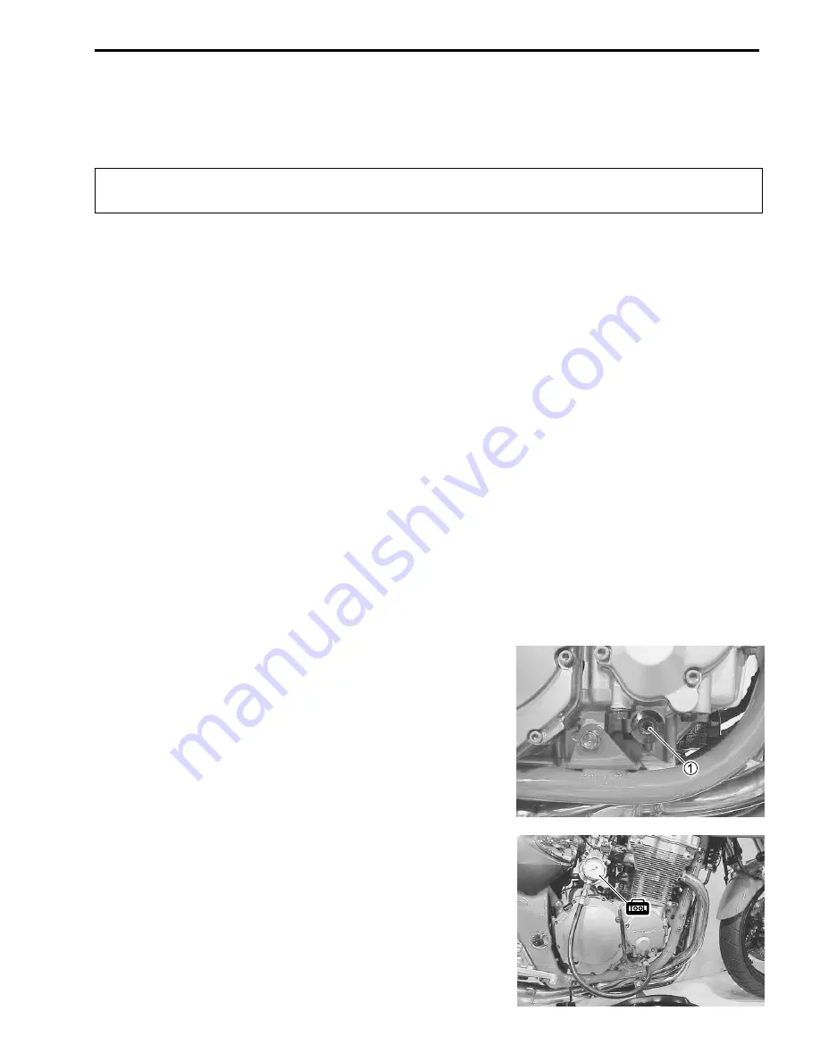
• Remove the main oil gallery plug 

1

.

• Install the oil pressure gauge and adaptor into the main oil

gallery.

• Warm up the engine as follows:

Summer: 10 min. at 2 000 r/min.
Winter: 20 min. at 2 000 r/min.

• After warm up, increase the engine speed to 3 000 r/min. (ob-

serve the tachometer), and read the oil pressure gauge.

&

09915-74510: Oil pressure gauge
09915-74540: Oil pressure gauge attachment
09915-77330: Meter (for high pressure)

)

Main oil gallery plug: 40 N.m (4.0 kgf.m, 29.0 lb-ft)

Summary of Contents for GSF600K1 2001

Page 1: ...9 9 5 0 0 3 6 1 0 2 0 1 E GSF600S GSF600...

Page 2: ...n der the motorcycle unsafe for the rider and passenger 2 3 4 5 GENERAL INFORMATION This manual has been prepared on the basis of the latest specifications at the time of pub lication If modifications...

Page 3: ...3 Holding the manual as shown at the right will allow you to find the first page of the section easily 4 The contents are listed on the first page of each section to help find the item and page you n...

Page 4: ...AD LOCK 1342 99000 32050 Apply THREAD LOCK SUPER 1360 99000 32130 Apply or use brake fluid Apply SUZUKI MOLY PASTE 99000 25140 Apply SUZUKI BOND 1207B 99000 31140 Apply THREAD LOCK SUPER 1303 99000 32...

Page 5: ...IONS 1 2 SUZUKI GSF600SY 2000 MODEL 1 4 SERIAL NUMBER LOCATION 1 4 FUEL AND OIL RECOMMENDATION 1 4 FUEL 1 4 ENGINE OIL 1 5 BRAKE FLUID 1 5 FRONT FORK OIL 1 5 BREAK IN PROCEDURES 1 5 CYLINDER IDENTIFIC...

Page 6: ...ust use good judgement and basic mechanical safety principles If you are unsure about how to perform a particular service operation ask a more experienced mechanic for ad vice GENERAL PRECAUTIONS Prop...

Page 7: ...lts and nuts tighten the larger sizes first Al ways tighten the bolts and nuts diagonally from the inside working out and to the specified tightening torque Whenever you remove oil seals gaskets packi...

Page 8: ...ining MTBE Methyl Tertiary Butyl Ether is permitted 4 Use of blended gasoline alcohol fuel is permitted provided that the fuel contains not more than 10 etha nol Gasoline alcohol fuel may contain up t...

Page 9: ...r a long period MULTIGRADE TEMP FRONT FORK OIL Use fork oil 10 or equivalent fork oil BREAK IN PROCEDURES During manufacture only the best possible materials are used and all machined parts are finish...

Page 10: ...ttached on the left frame pipe Attached on the right side of the rear fender 1 Noise label For E 03 33 2 Information label For E 03 28 33 3 Vacuum hose routing label For E 33 4 Fuel caution label For...

Page 11: ...62 6 mm 2 465 in Stroke 48 7 mm 1 917 in Compression ratio 11 3 1 Piston diplacement 600 cm3 36 6 cu in Carburetor KEIHIN CVR32SS four Air cleaner Non woven fabric element Starter system Electric star...

Page 12: ...park plug NGK CR9EK or DENSO U27ETR Battery 12 V 28 8 kC 8 Ah 10HR Generator Three phase A C Generator Main fuse 30 A Fuse 15 15 15 10 10 A Headlight 12 V 60 51 51 W Position light 12 V 5 W Except for...

Page 13: ...GENERAL INFORMATION 1 9 CODE COUNTRY or AREA E 02 England UK E 19 European markets E 24 Australia E 28 Canada COUNTRY OR AREA CODES The following codes stand for the applicable country ies and area s...

Page 14: ...UEL FILTER 2 11 ENGINE IDLE SPEED 2 11 THROTTLE CABLE PLAY 2 11 CARBURETOR SYNCHRONIZATION 2 12 EVAPORATIVE EMISSION CONTROL SYSTEM E 33 ONLY 2 12 PAIR AIR SUPPLY SYSTEM 2 13 CLUTCH CABLE PLAY 2 13 DR...

Page 15: ...I I I Spark plugs I R I R Exhaust pipe bolts and muffler bolts T T T Air cleaner I I R I Engine oil R R R R R Engine oil filter R R Fuel hose I I I I Replace every four years Fuel filter I R I R Engi...

Page 16: ...indicated below NOTE Before lubricating each part clean off any rusty spots and wipe off any grease oil dirt or grime Lubricate exposed parts which are subject to rust with a rust preventative spray e...

Page 17: ...fts are removed for servicing Valve clearance when cold IN 0 10 0 15 mm 0 004 0 006 in EX 0 18 0 23 mm 0 007 0 009 in NOTE The camshafts must be at positions A or B in order to check or adjust the val...

Page 18: ...T mark on the signal generator rotor with the center of the pickup coil Also position the notches 1 on the right end of each camshaft as shown Measure the valve clearances of the remaining valves D an...

Page 19: ...result SPARK PLUG INSTALLATION To avoid damaging the cylinder head threads first finger tighten the spark plug and then tighten it to the proper torque using the spark plug wrench Insert the spark plu...

Page 20: ...ffler mounting bolt 29 N m 2 9 kgf m 21 0 lb ft AIR CLEANER Inspect every 6 000 km 4 000 miles 6 months and re place every 18 000 km 11 000 miles 18 months Remove the seat and fuel tank 4 3 Remove the...

Page 21: ...nts up If driving under dusty conditions clean the air cleaner element more frequently The surest way to accelerate engine wear is to operate the engine without the element or to use a torn element Ma...

Page 22: ...upright Place an oil pan below the engine and drain the oil by remov ing the oil drain plug 1 and filler cap 2 Tighten the oil drain plug 3 to the specified torque and pour new oil through the oil fi...

Page 23: ...as described in the engine oil replacement procedure NECESSARY AMOUNT OF ENGINE OIL Oil change 3 3 L 3 5 2 9 US Imp qt Oil and filter change 3 5 L 3 7 3 1 US Imp qt Engine overhaul 4 6 L 4 9 4 0 US I...

Page 24: ...LE SPEED Inspect initially at 1 000 km 600 miles 1 month and ev ery 6 000 km 4 000 miles 6 months thereafter NOTE Make this adjustment when the engine is hot Start the engine turn the throttle stop sc...

Page 25: ...stance is felt Tighten the locknut 6 while holding the adjuster 4 Throttle cable play A 2 4 mm 0 08 0 16 in After the adjustment is completed check that handlebar movement does not raise the engine id...

Page 26: ...rn the adjuster 2 all the way into the clutch lever assembly Remove the clutch release cover Loosen the locknut 3 and turn out the adjusting screw 4 two or three rotations Then slowly turn in the adju...

Page 27: ...er chain adjustment Dry or rusted links Missing O ring seals Kinked or binding links If any defects are found the drive chain must be replaced NOTE When replacing the drive chain replace the drive cha...

Page 28: ...e nut 3 to the specified torque Tighten both chain adjuster bolts 1 securely Rear axle nut 65 N m 6 5 kgf m 47 0 lb ft Install a new cotter pin For E 03 28 33 25 35 mm 0 98 1 38 in CLEANING AND LUBRIC...

Page 29: ...e fluid level is below the lower limit line replen ish with brake fluid that meets the following specification Specification and Classification DOT 4 The brake system of this motorcycle is filled with...

Page 30: ...e the pads with new ones 5 42 and 52 Replace the brake pads as a set otherwise braking per formance will be adversely affected BRAKE PEDAL HEIGHT Loosen the locknut 1 Turn the push rod 2 until the bra...

Page 31: ...e free end of the hose into a receptacle Front brake Bleed air from the brake system Squeeze and release the brake lever several times in rapid succession and squeeze the lever fully without releasing...

Page 32: ...tuated by a pedal TIRES Inspect every 6 000 km 4 000 miles 6 months TIRE TREAD CONDITION Operating the motorcycle with excessively worn tires will decrease riding stability and consequently invite a d...

Page 33: ...60 ZR17 69 W for the rear BRIDGESTONE BT56R F The use of tires other than those specified may cause instability It is highly recommended to use the specified tires STEERING Inspect initially at 1 000...

Page 34: ...every 12 000 km 7 500 miles 12 months Inspect the front fork for oil leakage scoring or scratches on the outer surface of the inner tubes Replace any defective parts if necessary 5 15 REAR SUSPENSION...

Page 35: ...3 2 3 16 5 A Air bleeder valve front rear 8 0 8 6 0 B Brake disc bolt front rear 23 2 3 16 5 C Rear brake caliper mounting bolt 25 2 5 18 0 D Rear brake caliper housing bolt 30 3 0 21 5 E Rear brake m...

Page 36: ...PERIODIC MAINTENANCE 2 23 PERIODIC MAINTENANCE 2 23 PERIODIC MAINTENANCE 2 23 PERIODIC MAINTENANCE 2 23 PERIODIC MAINTENANCE 2 23...

Page 37: ...cm2 114 psi The difference in compression pressure between any two cyl inders is more than 200 kPa 2 kgf cm2 28 psi All compression pressure readings are below 1 000 kPa 10 kgf cm2 142 psi even when t...

Page 38: ...bove items HIGH OIL PRESSURE Engine oil viscosity is too high Clogged oil passage Combination of the above items OIL PRESSURE TEST PROCEDURE Start the engine and check if the oil pressure indicator li...

Page 39: ...SEMBLY 3 12 ENGINE COMPONENTS INSPECTION AND SERVICE 3 49 CAMSHAFT CYLINDER HEAD 3 49 CAM CHAIN TENSIONER 3 51 VALVE 3 52 VALVE GUIDE 3 55 VALVE SEAT 3 56 VALVE SPRING 3 59 CYLINDER 3 64 PISTON 3 64 P...

Page 40: ...d 3 14 and 41 Cylinder 3 15 and 40 Pistons 3 15 and 39 Starter motor 3 16 and 38 Generator 3 16 and 38 PAIR system 3 4 12 48 and 98 ENGINE LEFT SIDE See page Gearshift lever 3 5 and 11 Engine sprocket...

Page 41: ...e seat and side frame covers 5 5 and 6 Remove the fuel tank 4 3 Remove the fuel tank mounting bracket bolts 1 Remove the air cleaner box mounting bolts 2 Remove the document tray 3 Remove the battery...

Page 42: ...Disconnect the throttle position sensor lead wire coupler 5 Slightly move the air cleaner box backward Remove the carburetor assembly by disconnecting the starter cable 6 and throttle cables 7 Remove...

Page 43: ...ift lever by removing its mounting bolt Remove the engine sprocket cover by removing the bolts Remove the speed sensor rotor 4 Remove the engine sprocket nut 5 while depressing the rear brake pedal En...

Page 44: ...3 6 ENGINE Remove the eight exhaust pipe bolts Remove the muffler mounting bolts Remove the oil cooler hose union bolts 1 Remove the oil cooler by removing the mounting bolts 2...

Page 45: ...Suppport the engine with a proper engine jack Remove the frame down tube mounting bolts and nuts Remove the frame down tube 1 Remove the engine mounting bolts nuts spacer and brackets Gradually lower...

Page 46: ...use new nuts and tighten them to the specified torque NOTE When reusing the removed engine mounting bolts 2 and 4 apply a small quantity of the THREAD LOCK 1342 to their threads 99000 32050 THREAD LO...

Page 47: ...assembly connector remove all of the old sealer from the exhaust pipe and from inside the muffler Apply the exhaust gas sealer to both the inside and outside of the new exhaust pipe muffler assembly c...

Page 48: ...speed sensor rotor bolt 99000 32050 THREAD LOCK 1342 Tighten the speed sensor rotor bolt 2 to the specified torque Speed sensor rotor bolt 2 20 N m 2 0 kgf m 14 5 lb ft Before installing the engine sp...

Page 49: ...with a viscosity rating of 10W40 SAE into the en gine after overhauling it Start up the engine and allow it run for several minutes at idle speed and then stop the engine Wait three minutes and then c...

Page 50: ...reinstalled in their original positions ENGINE DISASSEMBLY Remove each PAIR valve pipe and hose Remove the oil filter 1 using the special tool 09915 40610 Oil filter wrench NOTE Refer to page 2 10 for...

Page 51: ...o position the notches 2 on the right end of each camshaft as shown Remove the cam chain guide 3 After removing the spring holder bolt 4 and spring 5 remove the cam chain tensioner 6 09911 73730 5 mm...

Page 52: ...escending order according to the numbers cast on the cylinder head Firmly grip the cylinder head at both ends and lift it straight up If the cylinder head does not come off lightly tap on the finless...

Page 53: ...less portions of it using a plastic mallet Be careful not to damage the fins when removing or han dling the cylinder block Scribe the cylinder number on the head of the respective pis tons Place a cle...

Page 54: ...al generator rotor 3 using the special tool 09900 00410 Hexagon wrench set Disconnect the oil pressure switch lead wire 4 Remove the signal generator stator along with the pickup coil 5 and oil pressu...

Page 55: ...lutch spring set bolts in a crisscross pattern Then remove the bolts 09920 34810 Starter clutch holder Remove the clutch pressure plate 2 clutch drive plates and clutch driven plates NOTE See page 3 6...

Page 56: ...holder Remove the washer 1 washer seat 2 and clutch sleeve hub 3 Remove the thrust washer 4 With the spacer and bearing removed the primary driven gear assembly can disengage from the primary drive ge...

Page 57: ...ft cam driven gear 2 09900 09004 Impact driver set NOTE When removing the gearshift cam driven gear do not lose the gearshifting pawl 3 pin 4 and spring 5 Remove the circlip 6 09900 06107 Snap ring pl...

Page 58: ...o use it in conjunction with the special tool when removing the starter clutch assembly Remove the starter clutch assembly 1 from the crankshaft using the special tool 09930 33720 Rotor remover NOTE S...

Page 59: ...countershaft bearing retainer 1 Remove the upper crankcase bolts and nut Remove the oil pan 2 Remove the shim 3 and O ring 4 Remove the oil sump filter 5 Remove the oil return pipe 6 Remove the lower...

Page 60: ...numerical order and then remove them NOTE Two allen bolts are located at position A to tighten the crank shaft 09914 25811 6 mm T type hexagon wrench Remove the oil return pipe B NOTE If it is diffic...

Page 61: ...po sitions When removing the crankshaft journal bearings be care ful not to scratch the crankcase and the crankshaft jour nal bearings Remove the countershaft assembly 5 and driveshaft assem bly 6 NOT...

Page 62: ...m 3 from the opposite side 09900 06107 Snap ring pliers Remove the circlip 4 and gearshift cam stopper 5 09900 06107 Snap ring pliers NOTE Rotate the bearing 6 in the crankcase by hand to inspect for...

Page 63: ...ENGINE 3 25 Remove the oil pump 1 09900 00410 Hexagon wrench set Remove the O rings and dowel pins...

Page 64: ...ings with new ones to prevent oil leak age Install the oil pump 4 into the lower crankcase with the three bolts and then tighten them to the specified torque NOTE Apply a small quantity of THREAD LOCK...

Page 65: ...Circlip 5 Spring 6 Circlip Always use new circlips 4 4 4 4 4 and 6 6 6 6 6 Position the gearshift cam in the neutral position as shown This will allow the gearshift forks and transmission gears to be...

Page 66: ...e sure that the countershaft assembly turns freely while holding the driveshaft assembly If it does not turn freely turn the gearshift cam to the neutral position When installing the crankshaft journa...

Page 67: ...haft assembly along with the cam chain into the upper crankcase Insert the right and left thrust bearings 5 with the oil grooves facing towards the crankshaft web 3 85 Clean the mating surfaces of the...

Page 68: ...3 30 ENGINE BOND 1207B should be applied to the following locations The line of BOND...

Page 69: ...gf m 16 5 lb ft Tighten the main oil gallery plug 1 to the specified torque Replace the O ring with a new one 09900 00410 Hexagon wrench set Main oil gallery plug 40 N m 4 0 kgf m 29 0 lb ft Tighten t...

Page 70: ...0 lb ft Replace the oil pan gasket with a new one to prevent oil leakage NOTE Install a new gasket washer to the oil pan bolt A as shown Use a new gasket washer to prevent oil leakage Install the cou...

Page 71: ...AD LOCK SUPER 1303 to the threads of the starter clutch mounting bolt 99000 32030 THREAD LOCK SUPER 1303 Hold the starter clutch assembly using the special tool and then tighten the starter clutch mou...

Page 72: ...aft with the circlip 09900 06107 Snap ring pliers Install the washer 2 pin 3 oil pump driven gear 4 and washer 5 Fix the oil pump driven gear with the circlip 09900 06107 Snap ring pliers Install the...

Page 73: ...sher 5 and clutch sleeve hub nut 6 as shown Tighten the clutch sleeve hub nut to the specified torque 09920 53740 Clutch sleeve hub holder Clutch sleeve hub nut 95 N m 9 5 kgf m 68 5 lb ft Insert the...

Page 74: ...spring set bolt 12 N m 1 2 kgf m 8 5 lb ft Apply a light coat of the recommended bond to the clutch cover gasket mating surface A as shown 99000 31140 SUZUKI BOND 1207B Install the dowel pins a new ga...

Page 75: ...0 lb ft Install the signal generator stator along with the pickup coil 1 Be sure to fit the slot B on the back surface of the signal gen erator rotor over the locating pin 2 on the end of crankshaft...

Page 76: ...OTE Apply SUZUKI SUPER GREASE A to the starter motor O ring Apply a small quantity of THREAD LOCK 1342 to the two bolts 99000 32050 THREAD LOCK 1342 99000 25010 SUZUKI SUPER GREASE A CYLINDER BLOCK ST...

Page 77: ...9000 25140 SUZUKI MOLY PASTE Place a cloth beneath the piston and install the circlips 2 NOTE Install the pistons with the arrow mark A facing towards the exhaust side Be sure to use new circlips Inst...

Page 78: ...pistons With pistons 2 and 3 in place install pistons 1 and 4 and then insert them into the respective cylinders 09916 74521 Holder body 09916 74530 Band bore 55 65 mm NOTE Do not overtighten the band...

Page 79: ...head nuts and washers must be installed in the cor rect position as shown A Copper washer with cap nut 8 pcs B Steel washer with normal nut 4 pcs Tighten the twelve 10 mm nuts in ascending order and...

Page 80: ...STE onto the camshaft journals A and do not leave any dry spots Also apply engine oil onto the camshaft jour nal holders 99000 25140 SUZUKI MOLY PASTE The exhaust camshaft has the embossed letters EX...

Page 81: ...Starting from the roller pin A that is directly above the arrow marked 2 count out 24 roller pins from the exhaust camshaft side going towards the intake camshaft side Engage the 24th roller pin B on...

Page 82: ...journal holder thrust surfaces may result if the camshaft journal holders are not tightened evenly Tighten the camshaft journal holder bolts to the specified torque Camshaft journal holder bolt 10 N m...

Page 83: ...olts to the specified torque Cam chain tensioner mounting bolt 7 N m 0 7 kgf m 5 0 lb ft Insert the spring into the cam chain tensioner and tighten the spring holder bolt 4 to the specified torque Spr...

Page 84: ...clearance 2 4 Apply a light coat of the recommended bond to the signal gen erator gasket mating surface A as shown 99000 31140 SUZUKI BOND 1207B Install a new gasket and the signal generator cover 1 N...

Page 85: ...e cylinder head Install the four gaskets onto each cylinder head cover union bolt 1 and tighten them to the specified torque Replace the gaskets with new ones to prevent oil leak age Cylinder head cov...

Page 86: ...oil filter gasket O ring has contacted the oil filter mounting surface Then tighten the oil filter two full turns using the special tool 09915 40610 Oil filter wrench NOTE Before installing the oil f...

Page 87: ...intake camshaft has the embossed letters IN CAM WEAR Worn down cams are often the cause of mistimed valve opera tion resulting in reduced power output Measure the cam height H using the micrometer Rep...

Page 88: ...de diameter of the camshaft journal holder and the out side diameter of the camshaft journal Replace the camshaft or the cylinder head depending upon which one exceeds the speci fication 09900 20602 D...

Page 89: ...ket bolt 25 N m 2 5 kgf m 18 0 lb ft CAM CHAIN TENSIONER The cam chain tensioner is maintained at the proper tension by an automatically adjusted tensioner Unlock the ratchet mechanism 1 and move the...

Page 90: ...spring 3 NOTE To remove the rocker arm shaft screw a 8 mm bolt into the rocker arm shaft end and then pull out the shaft Using the special tools compress the valve spring and remove the valve cotters...

Page 91: ...2 mm 0 008 in VALVE STEM RUNOUT Support the valve using V blocks as shown and check its runout using the dial gauge If the runout exceeds the service limit replace the valve 09900 20606 Dial gauge 1 1...

Page 92: ...deflection exceeds the service limit then determine whether the valve or the guide should be replaced with a new one 09900 20606 Dial gauge 1 100 mm 09900 20701 Magnetic stand Valve stem deflection IN...

Page 93: ...dle Install a ring onto each valve guide Be sure to use new rings Oil the stem hole of each valve guide and drive the guide into the guide hole using the valve guide installer 2 Valve guide 3 Cylinder...

Page 94: ...ust be within the following specification Valve seat width W Standard 0 9 1 1 mm 0 035 0 043 in If the valve seat is out of specification re cut the seat VALVE SEAT SERVICING The valve seats 1 for bot...

Page 95: ...tter one or two turns Measure the valve seat width W after every cut If the valve seat is pitted or burned use the 45 cutter to condi tion the seat some more NOTE Cut only the minimum amount necessary...

Page 96: ...y to clean up any burrs caused by the previ ous cutting operations Do not use lapping compound after the final cut is made The finished valve seat should have a velvety smooth finish but not a highly...

Page 97: ...sure that the length 1 is not less than 2 5 mm 0 10 in If this length becomes less than 2 5 mm 0 10 in replace the valve Valve stem end length Service Limit 2 5 mm 0 10 in VALVE SPRINGS The force of...

Page 98: ...e replace the shaft Rocker arm shaft O D Standard 11 973 11 984 mm 0 4714 0 4718 in 09900 20205 Micrometer 0 25 mm ROCKER ARM INSIDE DIAMETER INSPECTION Measure the rocker arm inside diameter in two d...

Page 99: ...staller Do not reuse the oil seals Insert the valves with their stems coated with molybdenum oil solution mixed engine oil moly paste Coat the entire stem making sure that there are no gaps When inser...

Page 100: ...Valve lifter attachment 09916 84511 Tweezers Be sure to install all of the parts in their original posi tions Apply engine oil to the rocker arm shaft sufficiently Install the rocker arms 2 the sprin...

Page 101: ...0 32050 THREAD LOCK 1342 Use a new O ring to prevent the joint from sucking in any air NOTE When replacing the intake pipes identify the different intake pipes according to each I D code 1 1 26E0 for...

Page 102: ...six places If any one of the measurements exceed the limit overhaul the cylinder and replace the piston with an oversize piston The remaining cylin ders must also be rebored accordingly otherwise the...

Page 103: ...groove clearance Service Limit 1st 0 18 mm 0 007 in 2nd 0 15 mm 0 006 in Piston ring groove width Standard 1st 1 02 1 04 mm 0 040 0 041 in 2nd 0 81 0 83 mm 0 032 0 033 in Oil 1 51 1 53 mm 0 059 0 060...

Page 104: ...using the small bore gauge If either is out of specification or the difference between these measurement is more than the limits replace the piston 09900 20602 Dial gauge 1 1000 mm 09900 22403 Small b...

Page 105: ...be installed in any posi tion When installing the spacer be careful not to allow its two ends to overlap in the groove A INCORRECT B CORRECT NOTE Install the pistons with the arrow mark facing towards...

Page 106: ...the clutch drive plates using vernier calipers If a clutch drive plate claw width is less than the service limit replace the clutch plates as a set 09900 20102 Vernier calipers Clutch drive plate claw...

Page 107: ...ring CLUTCH RELEASE ASSEMBLY Before removing the clutch release assembly operate the clutch lever by hand to inspect it for a smooth movement and any abnor mal noise If excessive resistance is felt cl...

Page 108: ...the gearshift shaft oil seal s lip for damage or wear If any defects are found replace the oil seal with a new one OIL SEAL REPLACEMENT Remove the gearshift shaft oil seal from the lower crankcase In...

Page 109: ...HAFT HOLE INSPECTION Check the gearshift shaft hole for damage or wear GEARSHIFT SHAFT REASSEMBLY When installing the gearshift shaft return spring position the stop per between the ends of the gearsh...

Page 110: ...replace the fork its respective gear or both The clearance for each of the three gearshift forks plays an im portant role in the smoothness and positiveness of the shifting action 09900 20803 Thickne...

Page 111: ...and slide it towards the 3rd 4th drive gears 4 09900 06107 Snap ring pliers Slide the 6th top and 2nd drive gears toward the 3rd 4th drive gears then remove the 2nd drive gear circlip 5 Remove the 2n...

Page 112: ...w driven gear bushing 3 washer and the 5th driven gear 4 Remove the circlip washer and 4th driven gear 5 09900 06107 Snap ring pliers Remove the 4th driven gear bushing 6 lock washers 3rd driven gear...

Page 113: ...attention to the following points NOTE Before installing the gears rotate the bearing by hand to in spect for abnormal noises and smooth rotation Replace the bearing if there is anything unusual Befo...

Page 114: ...ashers and circlips The cross sectional view shows the correct position of the gears bushings washers and circlips 3 77 When installing a new circlip pay attention to the direction of the circlip Fit...

Page 115: ...ountershaft 1 1st low driven gear 2 5th driven gear 3 4th driven gear 4 3rd driven gear 5 6th top driven gear 6 2nd driven gear 7 Driveshaft 8 Countershaft 1st low drive gear 9 5th drive gear 0 3rd 4t...

Page 116: ...3 78 ENGINE...

Page 117: ...uge If the clearance exceeds the limit measure the conrod big end width and crank pin width If any of the measurements are out of specification replace the defective part s 09900 20803 Thickness gauge...

Page 118: ...faces towards the intake side Conrod cap nut Initial 20 N m 2 0 kgf m 14 5 lb ft Final 35 N m 3 5 kgf m 25 5 lb ft 09900 22301 Plastigauge NOTE Never rotate the crankshaft or conrod when a piece of p...

Page 119: ...O D specification Code O D specification 1 33 992 34 000 mm 1 3383 1 3386 in 2 33 984 33 992 mm 1 3380 1 3383 in 3 33 976 33 984 mm 1 3376 1 3380 in 09900 20202 Micrometer 25 50 mm Bearing thickness...

Page 120: ...side Tighten the conrod cap nuts to the specified torque Conrod cap nut Initial 20 N m 2 0 kgf m 14 5 lb ft Final 35 N m 3 5 kgf m 25 5 lb ft Check that the conrod moves smoothly CRANKCASE CRANKSHAFT...

Page 121: ...gauge Crankshaft journal oil clearance Standard 0 020 0 044 mm 0 0008 0 0017 in Crankshaft journal oil clearance Service Limit 0 08 mm 0 0031 in If the width at the widest part of the compressed plast...

Page 122: ...1 2589 1 2592 in 09900 20202 Micrometer 25 50 mm Bearing thickness specification Color Part No Thickness Green 12229 27A00 0A0 1 1 486 1 490 mm 12229 27A10 0A0 2 0 0585 0 0587 in Black 12229 27A00 0B...

Page 123: ...clearance exceeds the standard range adjust the thrust clearance as follows Remove the right side thrust bearing and measure its thick ness using the micrometer If the thickness of the right side thru...

Page 124: ...ow 2 450 2 475 mm 0 0990 0 1000 in 12228 43415 0 0965 0 0974 in 2 540 2 565 mm White 2 475 2 500 mm 0 1000 0 1010 in 12228 43416 0 0974 0 0984 in After selecting a left side thrust bearing install it...

Page 125: ...embly Do not attempt to disassemble the oil pump assembly The oil pump is available only as an assembly INSTALLATION Refer to the engine reassembly and the engine installation sec tions to install the...

Page 126: ...e operation of the oil pressure regulator by pushing on the piston with an appropriately shaped tool If the piston does not operate replace the oil pressure regulator with a new one OIL SUMP FILTER CL...

Page 127: ...l Oil sump filter NOTE When installing the oil sump filter make sure that the arrow mark A points towards the front of the motorcycle Do not loose the O ring 1 and shim 2 Oil pressure regulator Oil pr...

Page 128: ...draining the engine oil remove the oil pressure switch and the oil cooler NOTE Refer to the following pages for the details of each step Drain Engine oil 2 9 Remove Signal generator cover Oil pressur...

Page 129: ...uck in the oil cooler fins us ing compressed air Inspect the oil cooler for oil leaks If any defects are found re place the oil cooler with a new one If the fins are bent or dented repair them by care...

Page 130: ...FILTER 2 10 OIL PRESSURE 2 25 OIL JET OIL JET for the cylinder head REMOVAL The oil jet for the cylinder head can be removed after remov ing the cylinder block NOTE Refer to the following pages for th...

Page 131: ...iston cooling 1 Oil jet for the transmission 2 INSPECTION Make sure that the oil jets are not clogged If they are clogged clean their oil passage using a wire of the proper size and com pressed air IN...

Page 132: ...OIL JET OIL JET OIL JET OIL PRESSURE SWITCH CRANKSHAFT JOURNALS COUNTERSHAFT LEFT SIDE BEARING NO 1 PISTON AND PISTON PIN STUD BOLTS EXHAUST SIDE PISTON CYLINDER WALL CONROD BIG END EXHAUST ROCKER ARM...

Page 133: ...ENGINE 3 95 ENGINE LUBRICATION SYSTEM...

Page 134: ...SYSTEM CHART UNION BOLT UNION BOLT OIL POOL OIL PIPE STUD BOLT STUD BOLT OIL PIPE OIL POOL OIL POOL OIL POOL ORIFICE ORIFICE UNION BOLT UNION BOLT OIL GALLERY OIL PUMP OIL SUMP FILTER CYLINDER HEAD C...

Page 135: ...ENGINE 3 97 CYLINDER HEAD COOLING SYSTEM...

Page 136: ...o 4 Remove the PAIR valve Remove the PAIR pipes from each cylinder PAIR SYSTEM INSTALLATION Installation is in the reverse order of removal 3 100 Tighten the PAIR valve mounting bolt to the specified...

Page 137: ...the vacuum port of the PAIR valve as shown in the photograph Apply negative pressure slowly to the PAIR valve and inspect the air flow If air does not flow out within the specification the PAIR valve...

Page 138: ...0 ENGINE PAIR Valve Clamp No 4 cy No 3 cy No 2 cy No 1 cy 10 N m 1 0 kgf m 7 0 lb ft Clamp 10 N m 1 0 kgf m 7 0 lb ft Vacuum hose To No 3 carburetor To air cleaner box PAIR AIR SUPPLY SYSTEM HOSE ROUT...

Page 139: ...REMOUNTING 4 6 CARBURETOR 4 7 CONSTRUCTION 4 7 SPECIFICATIONS 4 8 I D NO LOCATION 4 9 DIAPHRAGM AND PISTON OPERATION 4 10 SLOW SYSTEM 4 11 MAIN SYSTEM 4 12 STARTER ENRICHER SYSTEM 4 13 FLOAT SYSTEM 4...

Page 140: ...hose fuel filter fuel hose and carburetor assembly When there is negative pressure vacuum in the combustion chamber the fuel is able to flow from the fuel tank through the fuel valve and then to the c...

Page 141: ...the ON position Remove the fuel valve knob 2 by removing its mounting screw Disconnect the vacuum hose 3 fuel hose 4 and fuel tank drain hose 5 Gasoline is highly flammable and explosive Keep heat spa...

Page 142: ...e engine has started negative pressure vacuum A is generated in the combustion chamber and reaches the diaphragm through a passage in the carburetor s main bore and the vacuum hose This nega tive pres...

Page 143: ...The gaskets 2 and O ring 3 must be replaced with new ones to prevent fuel leakage INSPECTION AND CLEANING If the fuel filter is dirty with sediment or rust fuel will not flow smoothly and loss in engi...

Page 144: ...diment or rust fuel will not flow smoothly and loss in engine power may result Replace the fuel filter FUEL FILTER REMOUNTING Remount the fuel filter in the reverse order of removal Pay atten tion to...

Page 145: ...sket O ring F Float chamber G Drain screw H Vacuum inlet cap I Vacuum hose for fuel valve J Carburetor set shaft Upper and Lower K TPS Throttle position sensor L Air vent joint pipe M Air vent hose N...

Page 146: ...ling cable 0 08 0 16 in Starter enricher plunger cable 0 5 1 0 mm play 0 02 0 04 in ITEM SPECIFICATION E 19 U type E 33 Carburetor type KEIHIN CVR32SS Bore size 32 mm I D No 31F1 31F3 Idle r min 1 200...

Page 147: ...FUEL SYSTEM 4 9 I D NO LOCATION Each carburetor has an I D number 1 printed on its body...

Page 148: ...i A Negative pressure is admitted into the diaphragm chamber 2 through an orifice 3 provided in the piston valve 1 Rising negative pressure overcomes the spring 4 force causing the piston valve 1 to r...

Page 149: ...by the pilot jet 3 where it mixes with air coming in through the pilot air jet 4 This mixture rich with fuel then goes up through the pilot passage to the pilot screw 5 Part of the mixture is dischar...

Page 150: ...needle jet 5 mixes with the air admitted through the main air jet 6 and forms an emulsion The emulsified fuel then passes through the clearance between the needle jet 5 and jet needle 7 and is dischar...

Page 151: ...for starting This occurs when the mixture is sprayed through the starter outlet port 5 into the main bore NOTE A starter enricher system is operated almost the same way as a choke FLOAT SYSTEM The flo...

Page 152: ...el tank mounting bolts 1 Remove the air cleaner box mounting bolts 2 Disconnect the throttle position sensor coupler 3 Loosen the respective carburetor clamp screws Slightly move the air cleaner box 4...

Page 153: ...set at the factory Prior to disassembly mark the throttle position sensor s origi nal position with paint or a scribe for accurate reinstalla tion Avoid removing the throttle position sensor from the...

Page 154: ...hragm this may damage the dia phragm Remove the spring 2 and the piston valve along with its dia phragm 3 With the jet needle stopper 4 pinched remove it Remove the washer 5 E ring 6 washer 7 and jet...

Page 155: ...cher jet 0 Pilot screw NOTE Before removing the pilot screw 0 its setting must be determined Slowly turn the pilot screw clockwise and count the number of turns until it is lightly seated Make a note...

Page 156: ...lly drill through the plug Thread a self tapping sheet metal screw into the plug Pull on the screw head with pliers to remove the plug Carefully clean any metal shavings from the area Slowly turn the...

Page 157: ...ecessary to use a dip type cleaning solution and al low them to soak Always follow the chemical manufacturer s instructions for proper use and cleaning of the carburetor components After cleaning reas...

Page 158: ...w into the float chamber Clean the float chamber and float parts with gasoline If the needle valve is worn as shown in the illustration replace it along with a new valve seat Clean the fuel passage of...

Page 159: ...LOCK 1342 Face the stamped side of the throttle valve out PILOT SCREW After cleaning reinstall the pilot screw to the original setting by turning the screw in until it lightly seats and then backing i...

Page 160: ...throttle valve with the throttle lever Position the throttle position sensor until resistance 2 is 3 09 4 63 k When the resistance 2 is within specification tighten the throttle position sensor mount...

Page 161: ...owly turn the returning cable adjuster 2 to obtain a cable slack B of 1 0 mm 0 04 in Tighten the lock nut 1 securely After all of the work has been completed install the carburetor assembly onto the e...

Page 162: ...balancer s rubber hoses to this inlet 09913 13121 Carburetor balancer Start the engine and let it run at 1 750 r min Adjust the engine speed by turning the throttle stop screw Turn the air screw 1 of...

Page 163: ...o be used to synchronize the carburetors CARBURETOR SYNCHRONIZATION Remove all of the vacuum inlet caps before synchronizing the carburetors Connect the carburetor balancer hoses to these vacuum inlet...

Page 164: ...4 26 FUEL SYSTEM After balancing the carburetor set the engine speed by turning the throttle stop screw Observe the tachometer reading Engine speed 1 200 100 r min...

Page 165: ...DISPOSAL 5 38 REMOUNTING 5 39 FINAL INSPECTION AND ADJUSTMENT 5 40 SUSPENSION SETTING 5 40 FRONT BRAKE 5 41 CONSTRUCTION 5 41 BRAKE PAD REPLACEMENT 5 42 BRAKE FLUID REPLACEMENT 5 42 BRAKE CALIPER REMO...

Page 166: ...SSIS 3 5 kgf m 25 5 lb ft 35 N m Side cowling RH Wind screen Side cowling LH Front cowling Meter panel Center cowling Cowling brace Side cowling bracket RH Side cowling bracket LH EXTERIOR PARTS CONST...

Page 167: ...ept for GSF600 Remove the two screws Remove the rear view mirrors 1 and the front cowling 2 Hooked part Remove the side cowling 4 left and right Disconnect the turn signal lead wire coupler Remove the...

Page 168: ...sition light lead wire coupler Remove the headlight assy 6 Remove the screws both left and right side Remove the combination meter 7 6 33 Remove the three screws and the upper panel 8 Remove the wirin...

Page 169: ...ng the ignition key DOCUMENT TRAY Remove the seat 5 5 Remove the document tray 1 FRAME COVER Remove the seat 5 5 Remove the passenger grab handle 1 Disconnect the brake light taillight coupler 2 Remov...

Page 170: ...5 6 CHASSIS SIDE FRAME COVER Remove the side frame cover 1 left and right side REMOUNTING Remount the cowling cowling brace seat and frame covers in the reverse order of removal Hooked part...

Page 171: ...ont axle Spacer Collar Brake disc R Bearing R Spacer Bearing L Brake disc L Collar Front wheel Air valve Balancer Axle shaft Brake disc bolt FRONT WHEEL CONSTRUCTION ITEM N m kgf m lb ft A 65 6 5 47 0...

Page 172: ...7 0 lb ft 39 N m 3 9 kgf m 28 0 lb ft 23 N m 2 3 kgf m 16 5 lb ft 39 N m 3 9 kgf m 28 0 lb ft 23 N m 2 3 kgf m 16 5 lb ft Left Use old part Use old part Use old part Spacer Clearance Bearing installer...

Page 173: ...EEL BEARINGS Inspect the play of the wheel bearings by hand while they are in the wheel Rotate the inner race by hand to inspect it for abnormal noise and smooth rotation Replace the wheel bearings if...

Page 174: ...auge 1 100 mm 09900 20701 Magnetic stand 09900 21304 V block set 100 mm Wheel axle runout Service Limit 0 25 mm 0 010 in REASSEMBLY Apply SUZUKI SUPER GREASE A to the bearings before installation For...

Page 175: ...65 N m 6 5 kgf m 47 0 lb ft Tighten the front axle pinch bolts 2 to the specified torque Front axle pinch bolt 23 N m 2 3 kgf m 16 5 lb ft NOTE Before tightening the front axle nut and front axle nut...

Page 176: ...ter tube slide metal Oil lock piece Outer tube R Outer tube L Gasket Ring Cylinder Spring Inner tube Inner tube slide metal O ring Spacer Washer Spring Front fork cap bolt Front axle pinch bolt Cylind...

Page 177: ...bolts 1 left and right side Remove the front fender 2 Remove the brake hose clamp bolt 3 left and right side Loosen the front fork upper pinch bolt 4 NOTE Slightly loosen the front fork cap bolt 5 to...

Page 178: ...veral times to drain out fork oil Hold the front fork in the inverted position for a few minutes to allow the fork oil to fully drain Remove the dust seal 5 and oil seal stopper ring 6 Remove the cyli...

Page 179: ...ssembling the front fork Remove the following parts 1 Oil seal 2 Oil seal retainer 3 Outer tube slide metal 4 Inner tube slide metal 5 Oil lock piece INSPECTION INNER AND OUTER TUBES Inspect the inner...

Page 180: ...OIL SEAL Hold the inner tube vertically clean the metal groove and install the inner tube slide metal by hand Do not damage the Teflon coated surface of the inner tube s slide metal when mounting it I...

Page 181: ...the front fork protecter 9 NOTE Fit the projection of the front fork protecter to the depression of the front fork outer tube CYLINDER BOLT Apply THREAD LOCK 1342 1 to the cylinder bolt and tighten i...

Page 182: ...l level gauge Oil level 116 mm 4 6 in E 03 28 33 112 mm 4 4 in The other countries NOTE When adjusting the oil level remove the fork spring and compress the inner tube fully FORK SPRING Install the fo...

Page 183: ...11 NOTE Before tightening the front axle and front axle pinch bolt move the front fork up and down four or five times Tighten the front fork cap bolt 2 and front fork upper pinch bolt 3 Front fork ca...

Page 184: ...ebar 8 Handlebar balancer 9 Handlebar switch assy L 0 Handlebar switch assy R A Steering stem head nut B Handlebar holder bolt C Front fork upper pinch bolt D Steering stem nut E Front fork lower pinc...

Page 185: ...teering stem upper bracket 2 Remove the steering stem nut using the special tool 09940 14911 Steering stem nut wrench Remove the steering stem lower bracket NOTE Hold the steering stem lower bracket t...

Page 186: ...lower bearing inner race using a chisel The removed bearing inner race should be replaced with a new one Remove the steering stem upper and lower bearing races using the special tools 09941 54911 Bea...

Page 187: ...A For the other countries 99000 25010 SUZUKI SUPER GREASE A Install the bearings STEERING STEM NUT Tighten the steering stem nut to the specified torque using the special tool 09940 14911 Steering ste...

Page 188: ...acket Tighten the front fork lower pinch bolts 1 and front fork upper pinch bolt 2 to the specified torque Front fork lower pinch bolt 1 23 N m 2 3 kgf m 16 5 lb ft Front fork upper pinch bolt 2 23 N...

Page 189: ...same procedure on the end of the other handlebar 09940 92720 Spring scale Initial force 200 500 grams If the initial force reading is out of specification adjust the steering tension as follows 1 Firs...

Page 190: ...plate 2 Brake caliper bracket 3 Brake disc 4 Collar 5 Dust seal 6 Bearing R 7 Spacer 8 Bearing L 9 Retainer 0 Cushion A Rear sprocket bolt B Rear sprocket mounting drum C Rear sprocket D Bearing E Du...

Page 191: ...5 27 Left Right 23 N m 2 3 kgf m 16 5 lb ft 25 N m 2 5 kgf m 18 0 lb ft 100 N m 10 0 kgf m 72 5 lb ft For E 03 E 28 E 33 50 N m 5 0 kgf m 36 0 lb ft Left Right Spacer Clearance Bearing installer Left...

Page 192: ...e drive chain from the rear sprocket Remove the rear wheel Do not operate the brake pedal during or after rear wheel removal Draw out the rear sprocket mounting drum from the rear wheel NOTE Before se...

Page 193: ...in the rear sprocket mounting drum Rotate the inner race by hand to inspect it for abnormal noise and smooth rotation Replace the bearing if there is anything unusual Remove the rear sprocket mountin...

Page 194: ...unusual REAR SPROCKET Inspect the rear sprocket s teeth for wear If they are worn replace the sprockets and drive chain as a set A Normal wear B Excessive wear REASSEMBLY WHEEL BEARINGS Apply SUZUKI...

Page 195: ...n and free of any grease Apply THREAD LOCK SUPER 1360 to the brake disc bolts and tighten them to the specified torque 99000 32130 THREAD LOCK SUPER 1360 Brake disc bolt 23 N m 2 3 kgf m 16 5 lb ft Ti...

Page 196: ...5 Spacer 6 Bearing 7 Spacer 8 Bearing 9 Spacer 0 Spacer A Pivot shaft end cap B Washer C Spacer D Bearing E Spacer F Pivot shaft G Bearing H Chain buffer I Swingarm J Chain case K Chain adjuster L Cha...

Page 197: ...ASSIS 5 33 Left side Right side 50 N m 5 0 kgf m 36 0 lb ft 78 N m 7 8 kgf m 56 5 lb ft 50 N m 5 0 kgf m 36 0 lb ft 78 N m 7 8 kgf m 56 5 lb ft 78 N m 7 8 kgf m 56 5 lb ft 100 N m 10 0 kgf m 72 5 lb f...

Page 198: ...d hose clamps Handle brake fluid with care the fluid reacts chemically with paint plastics rubber materials etc Remove side frame cover left side only 5 6 Remove the rear shock absorber upper mounting...

Page 199: ...pacers from the swingarm and cushion lever Inspect the spacers for any flaws or other damage If any defects are found replace the spacers with new ones CHAIN BUFFER Remove the chain buffer 1 Inspect t...

Page 200: ...NGARM Inspect the swingarm for damage CUSHION LEVER NEEDLE BEARINGS Insert the spacers into the needle bearings move the spacer up and down and check for any play If there is excessive play replace th...

Page 201: ...a new one Do not attempt to disassemble the rear shock absorber It is unserviceable REASSEMBLY SWINGARM NEEDLE BEARINGS Before installing the needle bearings install the spacer Press the needle bearin...

Page 202: ...E BEARINGS Press the needle bearings into the cushion lever using the special tool 09941 34513 Steering outer race installer Apply SUZUKI SUPER GREASE A to the spacers and needle bearings For USA 9900...

Page 203: ...the specified torque Cushion lever rod mounting nut 1 78 N m 7 8 kgf m 56 5 lb ft Rear shock absorber lower mounting nut 2 50 N m 5 0 kgf m 36 0 lb ft Tighten the pivot shaft nut 3 to the specified t...

Page 204: ...EAR WHEEL 5 31 REAR BRAKE Bleed air from the brake system after remounting the brake caliper 2 18 FINAL INSPECTION AND ADJUSTMENT After installing the rear suspension and rear wheel adjust the followi...

Page 205: ...use cleaning solvent A contaminated brake disc or brake pad reduces braking performance Discard contaminated pads and clean the disc with high quality brake cleaner or a neutral detergent Handle brak...

Page 206: ...e plate as shown in the photograph Remount the reflector 6 For E 03 E 28 E 33 Tighten the brake caliper mounting bolts 5 to the specified torque Brake caliper mounting bolt 39 N m 3 9 kgf m 28 0 lb ft...

Page 207: ...CALIPER REMOVAL AND DISASSEMBLY Remove the reflector For E 03 E 28 E 33 Disconnect the brake hose from the brake caliper by removing the brake hose union bolt 1 and allow the brake fluid to drain into...

Page 208: ...iper piston damage Remove the dust seals and piston seals Do not reuse the dust seals and piston seals to prevent fluid leakage BRAKE CALIPER INSPECTION BRAKE CALIPER Inspect each brake caliper cylind...

Page 209: ...different types of fluid or cleaning solvents such as gasoline kerosine etc Replace the piston seals and dust seals with new ones Apply brake fluid to all of the seals brake caliper bores and pistons...

Page 210: ...rvice limit 09900 20606 Dial gauge 1 100 mm 09900 20701 Magnetic stand Brake disc runout Service Limit front and rear 0 3 mm 0 012 in BRAKE DISC REMOVAL AND REMOUNTING Remove the front and rear wheels...

Page 211: ...d Remove the brake hose union bolt and disconnect the brake hose Immediately wipe off any brake fluid contacting any part of the motorcycle The brake fluid reacts chemically with paint plastics and ru...

Page 212: ...ary cup and spring 3 Secondary cup 4 Piston 5 Primary cup 6 Spring MASTER CYLINDER INSPECTION MASTER CYLINDER Inspect the master cylinder bore for any scratches or other damage PISTON Inspect the pist...

Page 213: ...lvents such as gasoline kerosine etc Apply brake fluid to the master cylinder bore and all of the master cylinder components before reassembly Specification and classification DOT 4 When installing th...

Page 214: ...5 50 CHASSIS Tighten the brake hose union bolt to the specified torque Brake hose union bolt 23 N m 2 3 kgf m 16 5 lb ft Bleed air from the brake system after reassembling the master cylinder 2 18...

Page 215: ...aminated brake disc or brake pad reduces braking performance Discard contaminated pads and clean the disc with high quality brake cleaner or a neutral detergent Handle brake fluid with care the fluid...

Page 216: ...e pads as a set otherwise braking performance will be adversely affected Install the new brake pads and shims Be sure to properly install the shims 4 5 as shown in the illustration NOTE After replacin...

Page 217: ...later disassembly before removing the brake caliper mounting bolts Never reuse the brake fluid left over from previous servicing and which has been stored for long periods of time Brake fluid if it le...

Page 218: ...unout rear Service Limit 0 30 mm 0 012 in BRAKE CALIPER REASSEMBLY AND REMOUNTING Reassemble and remount the brake caliper in the reverse order of removal and disassembly Pay attention to the followin...

Page 219: ...r pistons all the way into the caliper Bleed air from the system after reassembling the brake caliper 2 18 Remove the reservoir mounting bolt 2 Place a rag underneath the brake hose union bolt on the...

Page 220: ...circlip 3 09900 06108 Snap ring pliers Remove the push rod 4 piston primary cup 5 and spring 6 MASTER CYLINDER INSPECTION MASTER CYLINDER Inspect the master cylinder bore for any scratches or other d...

Page 221: ...omponents When washing the components use the specified brake fluid Never use different types of fluid or cleaning solvents such as gasoline kerosine etc Apply brake fluid to the master cylinder bore...

Page 222: ...Tire tread depth Service Limit Front 1 6 mm 0 06 in Rear 2 0 mm 0 08 in Ply separation Tread separation Tread wear is extraordinarily deformed or distributed around the tire TIRE AND WHEEL TIRE REMOVA...

Page 223: ...ire lubricant to the tire bead When installing the tire onto the wheel observe the following points Do not reuse the valve which has been once removed NOTE When repairing a flat tire follow the repair...

Page 224: ...it the tire can burst and possibly cause injury Do not stand directly over the tire while inflating In the case of preset pressure air inflator pay special care for the set pressure adjustment In this...

Page 225: ...0 STARTER MOTOR REMOVAL AND DISASSEMBLY 6 21 STARTER MOTOR INSPECTION 6 21 STARTER MOTOR REASSEMBLY AND REMOUNTING 6 22 STARTER RELAY INSPECTION 6 23 SIDE STAND IGNITION INTERLOCK SYSTEM PART INSPECTI...

Page 226: ...each terminal for corrosion and contamination CLAMPS Refer to WIRE HARNESS CABLE AND HOSE ROUTING 7 12 for proper clamping procedures Bend the clamp properly as shown in the illustration When clampin...

Page 227: ...the MF battery is different from that of a conventional battery Do not replace the MF bat tery with a conventional battery CONNECTING THE BATTERY When disconnecting terminals from the battery for disa...

Page 228: ...rcycle and tester If the voltage and current values are not known begin mea suring in the highest range When measuring the resistance make sure that no voltage is applied If voltage is applied the tes...

Page 229: ...ELECTRICAL COMPONENTS 1 Turn signal side stand relay 2 Fuse box 3 Ignition switch 4 Handlebar switch R 5 Front brake light switch 6 Battery 7 Rear brake light switch 8 Throttle position sensor 9 Signa...

Page 230: ...ICAL SYSTEM A Clutch lever position switch B Handlebar switch L C Ignition coil D Main fuse E Starter relay F Ignitor G Horn H Starter motor I Generator J Speed sensor K Side stand switch L Gear posit...

Page 231: ...h is mounted on the rotor The stator windings are assembled on the inside of a laminated core that forms part of the generator housing A rectifier bridge which is connected to the stator windings cont...

Page 232: ...ed wires Faulty battery Faulty battery Abnormal driving condition Faulty battery Measure the charging voltage between the battery terminals 6 9 Incorrect Faulty stator coil or disconnected lead wires...

Page 233: ...ion when measuring the current When checking to find the excessive current leak remove the couplers and connectors one by one checking each part CHARGING OUTPUT INSPECTION Remove the seat 5 5 Remove t...

Page 234: ...mper housing 4 Oil seal 5 O ring 6 Spacer 7 Generator end housing 8 Bearing 9 Stud bolt 0 Retainer A Rotor B Bearing cover 2 C Slip ring side bearing D Bearing cover 1 E Generator hausing F Rectifier...

Page 235: ...wire disconnect the battery lead wire Remove the generator 3 Hold the generator driven gear using a vise 4 and two pieces of wood 5 as shown Then remove the generator driven gear nut Do not hold the d...

Page 236: ...g screws 3 Remove the rectifier 4 NOTE Straighten the stator coil lead wires using long nose pliers then remove the rectifier Remove the generator housing nuts Separate the generator housing 5 from th...

Page 237: ...INSPECTION ROTOR BEARINGS Inspect the rotor bearings for abnormal noise Also rotate the rotor bearings by hand and make sure that they rotate smoothly If there is anything unusual remove the bearing s...

Page 238: ...ntinuity replace the stator Also check that the stator is properly insulated 09900 25008 Multi circuit tester set Tester knob indication Continuity test ROTOR COIL CONTINUITY CHECK Measure the continu...

Page 239: ...Tester knob indication Continuity test P4 P3 P2 P1 Terminal Terminal Voltage 1 P1 P2 P3 P4 0 4 0 5 V P1 P2 P3 P4 1 1 4 1 5 V 2 P1 P2 P3 P4 1 4 1 5 V P1 P2 P3 P4 2 0 4 0 5 V RECTIFIER Measure the volt...

Page 240: ...A to the lip of the oil seal For USA 99000 25030 SUZUKI SUPER GREASE A For the other countries 99000 25010 SUZUKI SUPER GREASE A Apply a small quantity of THREAD LOCK 1342 to the bearing retainer scre...

Page 241: ...nut 4 5 N m 0 45 kgf m 3 5 lb ft Tighten the generator driven gear nut to the specified torque Generator driven gear nut 55 N m 5 5 kgf m 40 0 lb ft NOTE After tightening the generator driven gear nut...

Page 242: ...E STAND IGNITION INTERLOCK SYSTEM DESCRIPTION This side stand ignition interlock system prevents the motorcycle from being started with the side stand down The system is operated by an electric circui...

Page 243: ...Side stand Down OFF The current flow A switches on the side stand relay and the ignition coils send voltage to the spark plugs even when the side stand is kept down 2 Side stand Up ON The current flow...

Page 244: ...s pushed Faulty clutch lever position switch No good Voltage Faulty gear position switch Check the starter relay 6 23 OK Others Faulty side stand switch Check the side stand switch 6 25 Check if the s...

Page 245: ...otor as shown STARTER MOTOR INSPECTION CARBON BRUSHES Inspect the carbon brushes for abnormal wear cracks or smooth ness in the brush holder If either carbon brush is defective replace the brush assem...

Page 246: ...mature shaft If there is no continuity between the segments or there is con tinuity between the segments and shaft replace the armature with a new one OIL SEAL INSPECTION Check the seal lip for damag...

Page 247: ...Align the match marks on the starter motor case with the match mark on the housing end Apply a small quantity of THREAD LOCK 1342 to the starter motor housing bolts 99000 32050 THREAD LOCK 1342 Insta...

Page 248: ...is ok 09900 25008 Multi circuit tester set Tester knob indication Continuity test Do not apply battery voltage to the starter relay for more than five seconds This may overheat and damage the relay co...

Page 249: ...oupler and measure the volt age between Green and Black White lead wires 09900 25008 Multi circuit tester set Tester knob indication Diode test Blue Ground ON in neutral OFF not in neutral 09900 25008...

Page 250: ...09900 25008 Multi circuit tester set Tester knob indication Continuity test DIODE INSPECTION Measure the voltage between the terminals using the multi cir cuit tester Refer to the following table 099...

Page 251: ...s it induces the secondary current in the ignition coil s secondary windings and produces the spark between the spark plug gaps The ignition cutoff circuit is incorporated in the ignitor to prevent th...

Page 252: ...oor connection of related circuit couplers Faulty spark plugs Faulty ignitor Poor connection of ignition couplers Measure the ignition coil primary peak voltage 6 29 NOTE The ignition coil peak voltag...

Page 253: ...be NOTE Do not disconnect the ignition coil primary wire 09900 25008 Multi circuit tester set When using the multi circuit tester and peak volt adap tor refer to the appropriate instruction manual Shi...

Page 254: ...er knob indication Voltage Ignition coil primary peak voltage More than 140 V If the voltages are lower than the standard values inspect the ignition coil and the signal generator IGNITION COIL RESIST...

Page 255: ...e multi circuit tester and peak volt adap tor refer to the appropriate instruction manual Shift the transmission into neutral turn the ignition switch to the ON position and grasp the clutch lever Pre...

Page 256: ...is within specification but on the ignitor coupler is out of speci fication the wire harness must be replaced If both peak voltages are out of specification the signal generator must be replaced and r...

Page 257: ...mbination meter mounting nuts 2 Remove the combination meter 3 DISASSEMBLY Disassemble the combination meter as follows INSPECTION Measure the continuity between the lead wires in the diagram on the n...

Page 258: ...ND PILOT LAMP 11 NEUTRAL 12 HIGH BEAM 13 TURN L 14 IGNITION 15 Blank 16 GROUND TACHOMETER 11 10 9 8 7 6 5 4 3 2 1 12 14 13 15 16 HIGH BEAM TURN SIGNAL L TURN SIGNAL R NEUTRAL OIL TACHOMETER SPEEDOMETE...

Page 259: ...nect a 12 V battery between B and B W 10 k resistor Between B R and B and pocket tester tester probe to B and tester probe to B R as shown B R Black with Red tracer B W Black with White tracer B Black...

Page 260: ...switch to the ON position Check if the oil pressure indicator lights up when grounding the Green Yellow lead wire If the oil pressure indicator does not light up check the couplers If all of the conn...

Page 261: ...clean the bulb with a cloth moistened with alcohol or soapy wa ter to prevent premature bulb failure Headlight bulb 12 V 60 51 51 W Position light bulb 12 V 5 W Except for E 03 28 33 NOTE Adjust the h...

Page 262: ...you touch the bulb with your bare hands clean the bulb with a cloth moistened with alcohol or soapy water to prevent premature bulb failure Turn signal light bulb 12 V 21 W Do not overtighten the lens...

Page 263: ...Remove the seat 5 5 INSPECTION Before removing the turn signal side stand relay check the op eration of the turn signal light If the turn signal light does not illuminate inspect the bulb turn signal...

Page 264: ...URE SWITCH G Y Ground ON engine is stopped OFF engine is running NOTE Before inspecting the oil pressure switch check if the engine oil is at the proper level 2 9 WIRE COLOR B Black Lbl Light blue R R...

Page 265: ...NOTE First disconnect the battery lead wire A REMOUNTING Remount the battery in the reverse order of removal Type designation YTX9 BS Capacity 12 V 28 8 kC 8 Ah 10HR Standard electrolyte S G 1 320 at...

Page 266: ...t the nozzles of the electrolyte container 5 into the battery s electrolyte filler holes Hold the electrolyte container firmly so that it does not fall Do not allow any of the electrolyte to spill Mak...

Page 267: ...ry voltage with a tester The tester should indicate more than 12 5 12 6 V DC as shown If the battery voltage is lower than specification charge the battery with a battery charger NOTE Initial charging...

Page 268: ...ng current to exceed 4 A at any time After recharging wait at least 30 minutes and then measure the battery voltage using a tester If the battery voltage is less than 12 5 V recharge the battery again...

Page 269: ...7 16 FRONT BRAKE HOSE ROUTING 7 17 REAR BRAKE HOSE ROUTING 7 18 FRONT FOOTREST BRACKET SET UP 7 19 FUEL TANK SET UP 7 20 HIGH TENSION CORD ROUTING 7 21 MUFFLER MOUNTING 7 21 SIDE STAND AND CENTER STAN...

Page 270: ...tension cord 7 Defective signal generator 8 Defective ignitor No fuel reaching a carburetor 1 Clogged fuel tank vent hose 2 Clogged or defective fuel valve 3 Defective needle valve 4 Clogged fuel hose...

Page 271: ...cessive thrust clearance Noise seems to come from the transmission 1 Worn or rubbing gear 2 Worn countershaft spline 3 Worn driveshaft spline 4 Worn or rubbing primary gear 5 Worn bearing Adjust Repla...

Page 272: ...ace Replace Adjust or replace Replace Replace Replace Adjust float height Clean Synchronize Engine runs poorly in high speed range 1 Weak valve spring 2 Worn camshaft 3 Insufficient spark plug gap 4 M...

Page 273: ...e synchronizing screw 13 Air leakage from intake pipe 14 Excessive amount of engine oil Adjust Replace Adjust Rebore or replace Replace Repair or replace Clean or replace Replace Clean Adjust float he...

Page 274: ...jet 4 Improperly working throttle valve 5 Clogged fuel filter Clean Clean Clean Adjust Clean or replace Overflow and fuel level fluctuations 1 Worn or damaged needle valve 2 Broken needle valve sprin...

Page 275: ...related bearings Adjust Replace Replace Replace Rear suspension too noisy 1 Loose rear suspension fastener 2 Worn rear suspension bush 3 Worn swingarm bearing Tighten Replace Replace BRAKES Complaint...

Page 276: ...e Change to cold type spark plug Tune up Tighten Adjust carburetor Generator does not charge 1 Open or short in lead wires or loose lead connections 2 Shorted grounded or open generator coil 3 Shorted...

Page 277: ...is too old 6 Dirty container top and sides Check generator IC regulator or rectifier circuit connections and make necessary adjustment to obtain specified charging operation Replace battery and corre...

Page 278: ...Y W B Bl B Bl Y Bl Bl B Y B W W O W G Bl R B O Y Y W B Bl Y Bl O G W B Y B B W G B W G B W B Y B Y O W O W O W O W W W B Y O W O W W R R O O O Y O Y B W B W Gr Gr Br Br R O O Y B W Gr Br R R O O O Y...

Page 279: ...B Bl Bl G O Y O Y O B O B O G O G Lb Lbl Y W Y Y W O Y O O G R R Bl B Bl G O Y O B O G Lbl B Y B Y B W B W R R R R B Y B W R R B W B W B W B W Bl Y B W Bl Bl Y B Bl Y B B Y B Y B W B W W W O W O W G B...

Page 280: ...nly Clamp Wiring harness Rear turn signal RH Clamp Wiring harness Rear turn signal RH Clamp Wiring harness Clamp Wiring harness Clamp Wiring harness To rear turn signal LH To rear turn signal RH To CD...

Page 281: ...ensor To side stand switch Starter motor terminal To signal generator Clamp To turn signal LH Speedometer Clamp Clamp Clamp Wiring harness Clamp Wiring harness To speedometer To turn signal RH Wiring...

Page 282: ...Clamp Speed sensor Clamp Clamp Gear position switch lead wire Side stand switch lead wire Starter motor lead wire Engine oil hose Signal generator lead wire Engine ground wire Generator lead wire Engi...

Page 283: ...ttle cable No 1 Throttle cable No 2 Throttle cable No 2 Throttle cable No 2 Throttle cable No 1 Throttle cable No 1 Throttle cable No 1 4 6 mm 4 6 mm Carburetor Air cleaner box Breather hose Air vent...

Page 284: ...ING INFORMATION PAIR valve Clamp No 4 cy No 3 cy No 2 cy No 1 cy 10 N m 1 0 kgf m 7 0 lb ft Clamp 10 N m 1 0 kgf m 7 0 lb ft Vacuum hose To No 3 carburetor To air cleaner box PAIR AIR SUPPLY SYSTEM HO...

Page 285: ...ing the brake hose union to the stopper tighten the union bolt to the specified torque 5 21 Throttle cable 21 21 5 Brake hose No 1 Brake hose No 2 Clamp Brake caliper After touching the brake hose uni...

Page 286: ...pper tighten the union bolt to the specified torque Assemble the clamp as shown Reservoir tank White mark Master cylinder 10 11 mm 10 11 mm Brake caliper Brake hose guide Brake hose After touching the...

Page 287: ...SERVICING INFORMATION 7 19 Frame Footrest bracket Frame Washer Bolt Footrest bracket 2 0 mm FRONT FOOTREST BRACKET SET UP...

Page 288: ...NFORMATION Fuel tank cap Fuel tank Adhesive agent Fuel tank molding 4 4 N m 0 44 kgf m 3 0 lb ft Fuel tank front cushion Frame Fuel valve Fuel tank side cushion Fuel tank bracket 4 0 mm 4 0 mm 3 4 mm...

Page 289: ...4 Ignition coil No 2 No 3 90 90 90 90 90 90 Clamp 0 10 0 10 High tension cord No 2 High tension cord No 4 Plug cap Plug cap cover HIGH TENSION CORD ROUTING MUFFLER MOUNTING Muffler stay Spacer Cushio...

Page 290: ...7 22 SERVICING INFORMATION Spring Center stand Spring 5 0 kgf m 36 0 lb ft Spring Side stand Spring 40 N m 4 0 kgf m 29 0 lb ft 50 N m SIDE STAND SPRINGS CENTER STAND SPRINGS...

Page 291: ...TION 7 23 3 5 kgf m 25 5 lb ft 35 N m Side cowling RH Wind screen Side cowling LH Front cowling Meter panel Center cowling Cowling brace Side cowling bracket RH Side cowling bracket LH COWLING AND COW...

Page 292: ...7 24 SERVICING INFORMATION Side frame cover RH Side frame cover LH Frame cover Passenger grab handle FRAME COVER AND SIDE FRAME COVER SET UP...

Page 293: ...n meter panel Meter panel Meter panel tape No 1 Meter panel tape No 2 VIEW A A COWLING CUSHION AND TAPE Side cowling Reverse face Cushion Cushion Center cowling Reverse face Front cowling Reverse face...

Page 294: ...7 26 SERVICING INFORMATION FRONT FENDER CUSHION Cushion Front fender 5 mm 2 mm 2 mm 5 mm 2 mm 2 mm Cushion VIEW A A Seat support bracket Frame Seat lock set Clamp SEAT LOCK CABLE ROUTING...

Page 295: ...SERVICING INFORMATION 7 27 NOTE...

Page 296: ...7 28 SERVICING INFORMATION NOTE...

Page 297: ...0 25 mm 09900 20508 Cylinder gauge set 1 100 mm 40 80 mm 09900 20602 Dial gauge 1 1000 mm 09900 20605 Dial calipers 1 100 mm 10 34 mm 09900 20606 Dial gauge 1 100 mm 09900 20701 Magnetic stand 09900 2...

Page 298: ...re gauge 09915 77330 Meter for high pressure 09915 74540 Oil pressure gauge attachment 09916 10911 Valve lapper set 09916 14510 Valve lifter 09916 14910 Valve lifter attachment 09916 21111 Valve seat...

Page 299: ...9930 33720 Rotor remover 09940 14911 Steering stem nut wrench 09940 52861 Front fork oil seal installer 09940 92720 Spring scale 09941 34513 Steering outer race installer 09921 20220 Bearing remover s...

Page 300: ...bolt 150 15 0 108 5 Signal generator rotor bolt 25 2 5 18 0 Crankcase bolt nut M 6 11 1 1 8 0 M 8 23 2 3 16 5 Main oil gallery plug 40 4 0 29 0 Oil pump mounting bolt 10 1 0 7 0 Oil drain plug 23 2 3...

Page 301: ...front rear 23 2 3 16 5 Air bleeder valve front rear 8 0 8 6 0 Brake disc bolt front rear 23 2 3 16 5 Front footrest bolt 39 3 9 28 0 Front footrest bracket mounting bolt 23 2 3 16 5 Swingarm pivot nu...

Page 302: ...or 4 marked bolt 7 marked bolt A mm N m kgf m lb ft N m kgf m lb ft 4 1 5 0 15 1 0 2 0 2 1 5 5 3 0 3 2 0 5 0 5 3 5 6 6 0 6 4 5 10 1 0 7 0 8 13 1 3 9 5 23 2 3 16 5 10 29 2 9 21 0 50 5 0 36 0 12 45 4 5...

Page 303: ...de I D IN EX 5 000 5 012 0 1969 0 1973 Valve stem O D IN 4 965 4 980 0 1955 0 1961 EX 4 955 4 970 0 1950 0 1957 Valve stem runout IN EX 0 05 0 002 Valve face thickness IN EX 0 5 0 02 Valve stem end le...

Page 304: ...O D IN EX 11 973 11 984 0 4714 0 4718 Cylinder head distortion 0 20 0 008 CYLINDER PISTON PISTON RING Unit mm in ITEM STANDARD LIMIT Compression pressure 1 000 1 500 kPa 800 kPa 10 15 kgf cm2 8 kgf c...

Page 305: ...M STANDARD LIMIT Conrod small end I D 18 010 18 018 18 040 0 7091 0 7094 0 7102 Conrod big end side clearance 0 10 0 20 0 30 0 004 0 008 0 01 Conrod big end width 20 95 21 00 0 825 0 827 Crank pin wid...

Page 306: ...tch spring free length 47 6 1 87 TRANSMISSION DRIVE CHAIN Unit mm in Except ratio ITEM STANDARD LIMIT Primary reduction ratio 1 744 75 43 Final reduction ratio 3 133 47 15 Gear ratios 1st low 3 083 37...

Page 307: ...back Throttle cable play 2 0 4 0 mm pulling cable 0 08 0 16 in Starter enricher plunger cable 0 5 1 0 mm play 0 02 0 04 in CARBURETOR ITEM SPECIFICATION E 19 U type E 33 Carburetor type KEIHIN CVR32S...

Page 308: ...Ignition coil resistance Primary tap tap Tester range Approx 2 4 1 Secondary Spark plug cap Spark plug cap Tester range Approx 30 40 k 1 k Ignition coil primary peak More than 140 V voltage Generator...

Page 309: ...te light 5 BRAKE WHEEL Unit mm in ITEM STANDARD LIMIT Rear brake pedal height 50 2 0 Brake disc thickness Front 4 5 0 2 4 0 0 177 0 008 0 16 Rear 5 0 0 2 4 5 0 197 0 008 0 18 Brake disc runout 0 30 0...

Page 310: ...ing free length 356 14 0 Front fork oil level 116 4 6 E 03 28 33 112 The other 4 4 countries Rear wheel travel 126 5 0 Swingarm pivot shaft runout 0 3 0 01 TIRE ITEM STANDARD LIMIT Cold inflation tire...

Page 311: ...US lmp qt Front fork oil type Fork oil 10 Front fork oil capacity each leg 506 ml 17 1 17 8 US lmp oz E 03 28 33 510 ml The other 17 2 18 0 US Imp oz countries Brake fluid type DOT 4 R M 2 Use only un...

Page 312: ...e specifications and servicing procedures which differ from those of the GSF600SY 2000 model NOTE Any differences between the GSF600SY 2000 model and GSF600Y 2000 model in specifications and service d...

Page 313: ...troke 48 7 mm 1 917 in Piston displacement 600 cm3 36 6 cu in Compression ratio 11 3 1 Carburetor type number of carburetors KEIHIN CVR32 Four Air cleaner Non woven fabric element Starter system Elect...

Page 314: ...plug NGK CR9EK or DENSO U27ETR Battery 12 V 28 8 kC 8 Ah 10HR Generator Three phase A C generator Main fuse 30 A Fuse 15 15 15 10 10 A Headlight 12 V 60 55 W H4 Position light 12 V 5 W Turn signal lig...

Page 315: ...R REMOVAL Remove the headlight with two screws Disconnect the socket 1 and coupler 2 Remove the lead wires from the two clamps and disconnect the all lead wire couplers Remove the headlight housing 3...

Page 316: ...he combination meter in the re verse order of removal and disassembly DISASSEMBLY Disassemble the combination meter as follows INSPECTION Measure the continuity between the lead wires in the diagram o...

Page 317: ...ND PILOT LAMP 11 NEUTRAL 12 HIGH BEAM 13 TURN L 14 IGNITION 15 Blank 16 GROUND TACHOMETER 11 10 9 8 7 6 5 4 3 2 1 12 14 13 15 16 HIGH BEAM TURN SIGNAL L TURN SIGNAL R NEUTRAL OIL TACHOMETER SPEEDOMETE...

Page 318: ...55 W Position light bulb 12 V 5 W NOTE Adjust the headlight vertically and horizontally after reassembling BULB REPLACEMENT Remove the headlight with two screws 8 4 Disconnect the socket and coupler 8...

Page 319: ...out the bulb 4 Reassemble the headlight in the reverse order of disassembly HEADLIGHT BEAM ADJUSTMENT To adjust the beam horizontally Turn the adjuster 1 clockwise or counterclockwise To adjust the be...

Page 320: ...B Y B Y O W O W B Y O W O W O W W W R R O O O Y O Y B W B W Gr Gr Br Br O W W R O O Y B W Gr Br R R O O O Y O Y B W B W Gr Gr Br Br R O O Y B W Gr Br O G O G Gr Gr O O Y W Y W O B O B O W O W O G O G...

Page 321: ...turn signal RH Clamp Wiring harness Rear turn signal RH Clamp Wiring harness Clamp Wiring harness To rear turn signal LH To rear turn signal RH To CDI unit Wiring harness Clamp Thermo switch Clamp Cla...

Page 322: ...mp Clamp Front turn signal Handle switch RH and LH Speedometer Starter motor Starter motor Clamp Clamp CDI unit Clamp Clamp Clamp Wiring harness Starter relay Signal generator Side stand switch Gear p...

Page 323: ...uching the brake hose union to the stopper tighten the union bolt to the specified torque 5 21 Throttle cable 14 21 5 Brake hose No 1 Brake hose No 2 Clamp Brake caliper After touching the brake hose...

Page 324: ...4 Valve guide I D IN EX 5 000 5 012 0 1969 0 1973 Valve stem O D IN 4 965 4 980 0 1955 0 1961 EX 4 955 4 970 0 1950 0 1957 Valve stem runout IN EX 0 05 0 002 Valve face thickness IN EX 0 5 0 02 Valve...

Page 325: ...O D IN EX 11 973 11 984 0 4714 0 4718 Cylinder head distortion 0 20 0 008 CYLINDER PISTON PISTON RING Unit mm in ITEM STANDARD LIMIT Compression pressure 1 000 1 500 kPa 800 kPa 10 15 kgf cm2 8 kgf cm...

Page 326: ...STANDARD LIMIT Conrod small end I D 18 010 18 018 18 040 0 7091 0 7094 0 7102 Conrod big end side clearance 0 10 0 20 0 30 0 004 0 008 0 01 Conrod big end width 20 95 21 00 0 825 0 827 Crank pin width...

Page 327: ...h spring free length 47 6 1 87 TRANSMISSION DRIVE CHAIN Unit mm in Except ratio ITEM STANDARD LIMIT Primary reduction ratio 1 744 75 43 Final reduction ratio 3 133 47 15 Gear ratios 1st low 3 083 37 1...

Page 328: ...t mm in ITEM SPECIFICATION NOTE Ignition timing 13 B T D C at 1 500 r min Firing order 1 2 4 3 Spark plug Type NGK CR9EK DENSO U27ETR Gap 0 6 0 7 0 024 0 028 Spark performance Over 8 0 3 at 1 atm Pick...

Page 329: ...4 Speedometer light LED Tachometer light LED Turn signal indicator light LED 2 High beam indicator light LED Neutral position indicator light LED Oil pressure indicator light LED License plate light...

Page 330: ...J17 MT3 50 Rear J17 MT4 50 SUSPENSION Unit mm in ITEM STANDARD LIMIT NOTE Front fork stroke130 5 1 Front fork spring free length 358 14 1 Front fork oil level 114 4 5 Rear wheel travel 126 5 0 Swinga...

Page 331: ...ine oil type SAE 10W 40 API SF or SG Engine oil capacity Change 3 300 ml 3 5 2 9 US lmp qt Filter 3 500 ml change 3 7 3 1 US lmp qt 4 600 ml Overhaul 4 9 4 0 US lmp qt Front fork oil type Fork oil 10...

Page 332: ...GSF600SK1 GSF600SUK1 GSF600K1 2001 MODEL 9 1 9 GSF600SK1 GSF600SUK1 GSF600K1 2001 MODEL SPECIFICATIONS 9 2 SERVICE DATA GSF600 9 3 GSF600S GSF600SU 9 11 CHANGE 9 20 CONTENTS...

Page 333: ...able Front suspension stroke 130 mm 5 1 in Rear wheel travel 126 mm 5 0 in Caster 24 55 GSF600 25 00 GSF600S Trail 99 mm 3 90 in GSF600 98 mm 3 86 in GSF600S Steering angle 35 right left Turning radiu...

Page 334: ...N EX 0 35 0 014 Valve guide I D IN EX 5 000 5 012 0 1969 0 1973 Valve stem O D IN 4 965 4 980 0 1955 0 1961 EX 4 955 4 970 0 1950 0 1957 Valve stem runout IN EX 0 05 0 002 Valve face thickness IN EX 0...

Page 335: ...arm shaft O D IN EX 11 973 11 984 0 4714 0 4718 Cylinder head distortion 0 20 0 008 CYLINDER PISTON PISTON RING Unit mm in ITEM STANDARD LIMIT Compression pressure 1 000 1 500 kPa 800 kPa 10 15 kgf cm...

Page 336: ...mm in ITEM STANDARD LIMIT Conrod small end I D 18 010 18 018 18 040 0 7091 0 7094 0 7102 Conrod big end side clearance 0 10 0 20 0 30 0 004 0 008 0 01 Conrod big end width 20 95 21 00 0 825 0 827 Cran...

Page 337: ...0 004 Clutch spring free length 47 6 1 87 TRANSMISSION DRIVE CHAIN Unit mm in Except ratio ITEM STANDARD LIMIT Primary reduction ratio 1 744 75 43 Final reduction ratio 3 133 47 15 Gear ratios 1st low...

Page 338: ...CTRICAL Unit mm in ITEM SPECIFICATION NOTE Ignition timing 13 B T D C at 1 500 r min Firing order 1 2 4 3 Spark plug Type NGK CR9EK DENSO U27ETR Gap 0 6 0 7 0 024 0 028 Spark performance Over 8 0 3 at...

Page 339: ...l light 21 4 Speedometer light LED Tachometer light LED Turn signal indicator light LED 2 High beam indicator light LED Neutral position indicator light LED Oil pressure indicator light LED License pl...

Page 340: ...size Front J17 MT3 50 Rear J17 MT4 50 SUSPENSION Unit mm in ITEM STANDARD LIMIT NOTE Front fork stroke 130 5 1 Front fork spring free length 358 14 1 Front fork oil level 114 4 5 Rear wheel travel 126...

Page 341: ...lmp gal Engine oil type SAE 10W 40 API SF or SG Engine oil capacity Change 3 300 ml 3 5 2 9 US lmp qt Filter 3 500 ml change 3 7 3 1 US lmp qt 4 600 ml Overhaul 4 9 4 0 US lmp qt Front fork oil type F...

Page 342: ...tion IN EX 0 35 0 014 Valve guide I D IN EX 5 000 5 012 0 1969 0 1973 Valve stem O D IN 4 965 4 980 0 1955 0 1961 EX 4 955 4 970 0 1950 0 1957 Valve stem runout IN EX 0 05 0 002 Valve face thickness I...

Page 343: ...arm shaft O D IN EX 11 973 11 984 0 4714 0 4718 Cylinder head distortion 0 20 0 008 CYLINDER PISTON PISTON RING Unit mm in ITEM STANDARD LIMIT Compression pressure 1 000 1 500 kPa 800 kPa 10 15 kgf c...

Page 344: ...mm in ITEM STANDARD LIMIT Conrod small end I D 18 010 18 018 18 040 0 7091 0 7094 0 7102 Conrod big end side clearance 0 10 0 20 0 30 0 004 0 008 0 01 Conrod big end width 20 95 21 00 0 825 0 827 Cran...

Page 345: ...0 004 Clutch spring free length 47 6 1 87 TRANSMISSION DRIVE CHAIN Unit mm in Except ratio ITEM STANDARD LIMIT Primary reduction ratio 1 744 75 43 Final reduction ratio 3 133 47 15 Gear ratios 1st low...

Page 346: ...7 8 turns back Throttle cable play 2 0 4 0 mm pulling cable 0 08 0 16 in Starter enricher plunger cable 0 5 1 0 mm play 0 02 0 04 in CARBURETOR ITEM SPECIFICATION E 19 U type E 33 Carburetor type KEIH...

Page 347: ...han 1 0 V Ignition coil resistance Primary tap tap Tester range Approx 2 4 1 Secondary Spark plug cap Spark plug cap Tester range Approx 30 40 k 1 k Ignition coil primary peak More than 140 V voltage...

Page 348: ...cense plate light 5 BRAKE WHEEL Unit mm in ITEM STANDARD LIMIT Rear brake pedal height 50 2 0 Brake disc thickness Front 4 5 0 2 4 0 0 177 0 008 0 16 Rear 5 0 0 2 4 5 0 197 0 008 0 18 Brake disc runou...

Page 349: ...t fork spring free length 356 14 0 Front fork oil level 116 4 6 E 03 28 33 112 The other 4 4 countries Rear wheel travel 126 5 0 Swingarm pivot shaft runout 0 3 0 01 TIRE ITEM STANDARD LIMIT Cold infl...

Page 350: ...l 4 9 4 0 US lmp qt Front fork oil type Fork oil 10 Front fork oil capacity each leg 506 ml 17 1 17 8 US lmp oz E 03 28 33 510 ml The other 17 2 18 0 US Imp oz countries Brake fluid type DOT 4 R M 2 U...

Page 351: ...9 20 GSF600SK1 GSF600SUK1 GSF600K1 2001 MODEL CHANGE The gasket washer has been added to the lower crankcase LOWER CRANKCASE Gasket washer...

Page 352: ...E 10 20 FUEL LEVEL METER 10 21 WIRING DIAGRAM GSF600S 10 22 WIRING DIAGRAM GSF600 10 24 WIRE HARNESS ROUTING GSF600S 10 25 WIRE HARNESS ROUTING GSF600 10 26 NOTE The specification and service data are...

Page 353: ...Rear wheel travel 126 mm 5 0 in Caster 24 55 GSF600 25 00 GSF600S Trail 99 mm 3 90 in GSF600 98 mm 3 86 in GSF600S Steering angle 35 right left Turning radius 2 8 m 9 2 ft Front brake Disk brake twin...

Page 354: ...0 35 0 014 Valve guide I D IN EX 5 000 5 012 0 1969 0 1973 Valve stem O D IN 4 965 4 980 0 1955 0 1961 EX 4 955 4 970 0 1950 0 1957 Valve stem runout IN EX 0 05 0 002 Valve face thickness IN EX 0 5 0...

Page 355: ...aft O D IN EX 11 973 11 984 0 4714 0 4718 Cylinder head distortion 0 20 0 008 CYLINDER PISTON PISTON RING Unit mm in ITEM STANDARD LIMIT Compression pressure 1 000 1 500 kPa 800 kPa 10 15 kgf cm2 8 kg...

Page 356: ...ITEM STANDARD LIMIT Conrod small end I D 18 010 18 018 18 040 0 7091 0 7094 0 7102 Conrod big end side clearance 0 10 0 20 0 30 0 004 0 008 0 01 Conrod big end width 20 95 21 00 0 825 0 827 Crank pin...

Page 357: ...0 004 Clutch spring free length 47 6 1 87 TRIVE TRAIN Unit mm in Except ratio ITEM STANDARD LIMIT Primary reduction ratio 1 744 75 43 Final reduction ratio 3 133 47 15 Gear ratios 1st low 3 083 37 12...

Page 358: ...rns back Throttle cable play 2 0 4 0 mm pulling cable 0 08 0 16 in Starter enricher plunger cable 0 5 1 0 mm play 0 02 0 04 in CARBURETOR ITEM SPECIFICATION E 19 U type E 33 Carburetor type KEIHIN CVR...

Page 359: ...V Ignition coil resistance Primary tap tap Tester range Approx 2 4 1 Secondary Spark plug cap Spark plug cap Tester range Approx 30 40 k 1 k Ignition coil primary peak More than 140 V voltage Generat...

Page 360: ...plate light 5 BRAKE WHEEL Unit mm in ITEM STANDARD LIMIT Rear brake pedal height 50 2 0 Brake disc thickness Front 4 5 0 2 4 0 0 177 0 008 0 16 Rear 5 0 0 2 4 5 0 197 0 008 0 18 Brake disc runout 0 30...

Page 361: ...free length 356 14 0 Front fork oil level 116 4 6 E 03 28 33 112 The other 4 4 countries Rear wheel travel 126 5 0 Swingarm pivot shaft runout 0 3 0 01 TIRE ITEM STANDARD LIMIT Cold inflation tire pr...

Page 362: ...4 0 US lmp qt Front fork oil type Fork oil 10 Front fork oil capacity each leg 506 ml 17 1 17 8 US lmp oz E 03 28 33 510 ml The other 17 2 18 0 US Imp oz countries Brake fluid type DOT 4 R M 2 Use onl...

Page 363: ...de I D IN EX 5 000 5 012 0 1969 0 1973 Valve stem O D IN 4 965 4 980 0 1955 0 1961 EX 4 955 4 970 0 1950 0 1957 Valve stem runout IN EX 0 05 0 002 Valve face thickness IN EX 0 5 0 02 Valve stem end le...

Page 364: ...haft O D IN EX 11 973 11 984 0 4714 0 4718 Cylinder head distortion 0 20 0 008 CYLINDER PISTON PISTON RING Unit mm in ITEM STANDARD LIMIT Compression pressure 1 000 1 500 kPa 800 kPa 10 15 kgf cm2 8 k...

Page 365: ...ITEM STANDARD LIMIT Conrod small end I D 18 010 18 018 18 040 0 7091 0 7094 0 7102 Conrod big end side clearance 0 10 0 20 0 30 0 004 0 008 0 01 Conrod big end width 20 95 21 00 0 825 0 827 Crank pin...

Page 366: ...0 004 Clutch spring free length 47 6 1 87 TRIVE TRAIN Unit mm in Except ratio ITEM STANDARD LIMIT Primary reduction ratio 1 744 75 43 Final reduction ratio 3 133 47 15 Gear ratios 1st low 3 083 37 12...

Page 367: ...AL Unit mm in ITEM SPECIFICATION NOTE Ignition timing 4 B T D C at 1 200 r min Firing order 1 2 4 3 Spark plug Type NGK CR9EK DENSO U27ETR Gap 0 6 0 7 0 024 0 028 Spark performance Over 8 0 3 at 1 atm...

Page 368: ...ht 21 4 Speedometer light LED Tachometer light LED Turn signal indicator light LED 2 High beam indicator light LED Neutral position indicator light LED Oil pressure indicator light LED License plate l...

Page 369: ...r 17 MT4 50 17 M C MT4 50 SUSPENSION Unit mm in ITEM STANDARD LIMIT NOTE Front fork stroke 130 5 1 Front fork spring free length 358 14 1 Front fork oil level 114 4 5 Rear wheel travel 126 5 0 Swingar...

Page 370: ...l Engine oil type SAE 10W 40 API SF or SG Engine oil capacity Change 3 300 ml 3 5 2 9 US lmp qt Filter 3 500 ml change 3 7 3 1 US lmp qt 4 600 ml Overhaul 4 9 4 0 US lmp qt Front fork oil type Fork oi...

Page 371: ...resistance measured is out of the specification replace the gauge assembly with a new one INSTALLATION Install the fuel level gauge in the reverse order of removal Pay attention to the following poin...

Page 372: ...the meter indication wait at least for 20 seconds after the float position has been changed Resistance Float position 90 93 Empty E 8 10 Full F Connect a new fuel level gauge or correct fuel level gau...

Page 373: ...l G O Y O B O G Lbl B Y B Y B W B W R R R R B Y B W R R B W B W B W B W Bl Y B Br Bl Bl Y B Bl Y B B Y B Y B W B W W W O W O W B Br B Br G Bl G Bl R B R B O Y O Y Y W Y W B Bl B Bl Y Bl Bl B Y B W W O...

Page 374: ...Y W B Bl B Bl Y Bl Bl B Y B W W O W B Br G Bl R B O Y Y W B Bl Y Bl O G W B G B W G B W B Y B Y O W O W O W O W W W B Y O W O W W R R O O O Y O Y B W B W Gr Gr Br Br R O O Y B W Gr Br R R O O O Y O Y...

Page 375: ...G W B Y G O G Gr O Y W O B O W O G W B Y G O Bl Gr O R Y W O B O W B R B Bl Y G R O R P B G Y B Y B W B Lg O G Y Bl B B W Y B Gr R O P G Y B Y B W B Lg O G Y L B B W Y B Gr R O P G Y B Y B W B Lg O G...

Page 376: ...lamp Wiring harness Rear turn signal RH Clamp Wiring harness Battery Clamp Wiring harness Clamp Wiring harness TPS Carburetor heater E 02 only Clamp Wiring harness Clamp Handle switch LH and RH Carbur...

Page 377: ...lamp Wiring harness Rear turn signal RH Clamp Wiring harness Battery Clamp Wiring harness Clamp Wiring harness TPS Carburetor heater E 02 only Clamp Wiring harness Clamp Handle switch LH and RH Carbur...

Page 378: ...ess CDI unit Clamp Neutral switch Side stand switch Wiring harness Starter motor Clamp To signal generator Starter motor terminal Speed sensor To side stand switch Clamp Front turn signal LH Wiring ha...

Page 379: ...Prepared by Overseas Service Department 3rd Ed December 2001 1st Ed December 1999 Part No 99500 36102 01E Printed in Japan 384...

Page 380: ...Printed in Japan Y K1 K2...

Reviews: