background image

25

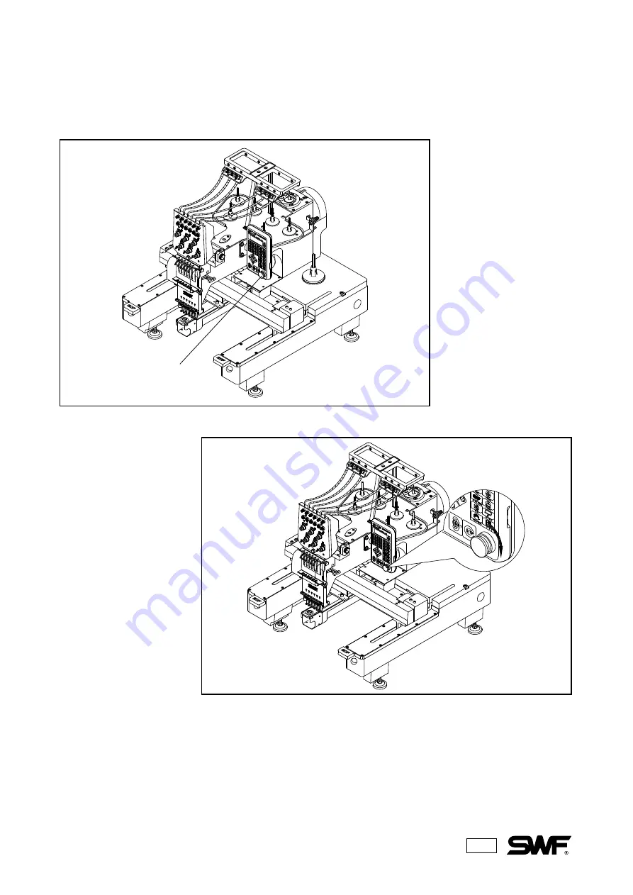
EMERGENCY STOP BUTTON

Emergency Stop Switch

If you need to stop the machine due to something as simple as a thread break or as serious as hitting a frame,

press the EMERGENCY STOP button. The machine will stop immediately.

To restart the machine, rotate the main shaft to the 100 degree mark and then turn the EMERGENCY

STOP button to the right (see arrow in diagram).

Summary of Contents for SWF/B Series

Page 1: ...M MM ME E 1 11 10 01 10 03 3 USER S MANUAL Single Head Automatic Embroidery Machine Compact Type S Su un nS St ta ar r C CO O L LT TD D SWF B Series ...

Page 2: ...TENTS IN THIS INSTRUCTION MAY CHANGE WITHOUT PRIOR NOTICE FOR IMPROVEMENT OF MACHINE QUALITY AND THUS MAY NOT CORRESPOND TO THE MACHINE YOU PURCHASED CONTACT YOUR SALES AGENT FOR INQUIRIES 3 THIS IS DESIGNED AND MANUFACTURED AS AN INDUSTRIAL MACHINE IT SHOULD NOT BE USED FOR OTHER THAN INDUSTRIAL PURPOSE ...

Page 3: ...maintenance needs and its operation will make you more comfortable with your purchase Knowledge of your equipment and confidence in its operation can only benefit your business from both a safety standpoint and in more efficient production We urge you to read your manual and mark any sections that you wish to discuss with your installation technician customer support or during any training session...

Page 4: ...APTER 5 BASIC MACHINE OPERATION 20 CHAPTER 6 BUTTON AND SWITCH OPERATION 21 CHAPTER 7 THREADING AND TENSION 27 The Upper Thread Path Threading the Machine Tension control on Upper Thread Take up Spring Bobbin Threading and Tension Adjustment Bobbin Winder CHAPTER 8 THE NEEDLE THE HOOK AND THE STITCHES 34 Stitch Formation The Needle and Hook The Needle Changing the Needle Relationship Between Needl...

Page 5: ...ELETE DESIGN COPY MEMORY INITIAL Basic Set up Functions X Scale Y Scale Angle Mirror Start ST X Satin Y Satin Sub Work Bobbin Winding Design Trace Length Measure Optimize Trace Repetition Work Embroidery Data Set up Embroidery Design Editing Stitch Edit Design Divide Design Filtering Speed Code Frame Movement Data Origin Power Resume Float Non stitching Movement Machine Data Set up The Floppy Driv...

Page 6: ...CHAPTER 12 THE CONTROL BOX 119 CHAPTER 13 MAINTENANCE AND INSPECTION 121 Oil Supply Grease Supply CHAPTER 14 MACHINE ADJUSTMENTS 128 CHAPTER 15 TROUBLESHOOTING 140 CHAPTER 16 NEEDLE CHART 150 CHAPTER 17 BACKING 151 CHAPTER 18 HOOPING AND TENSIONS 152 ...

Page 7: ...R When moving handling installing or performing maintenance on your machine it is important to observe all DANGER signals WARNING When operating the machine observe all WARNING signs in order to protect against personal injury CAUTION Follow all CAUTION signs to safeguard your machine during installation in your work environment NOTICE When operating the machine observe NOTICE signs in order to pr...

Page 8: ... When using a forklift make sure all helpers are out of the way of the moving equipment Make sure that all obstacles in the path of the forklift are removed Ensure that the size and the power of the forklift is sufficient to support the machine Place the machine in the center of the forklift arm and lift it carefully to maintain the weight balance DANGER Safeguarding your machine begins with deliv...

Page 9: ...ous injuries or machine damages Abrupt stop during the machine delivery or external shocks may also overturn the machine MACHINE OPERATION 1 Dress for safety Long unbound hair jewelry such as necklaces bracelets dangling earrings and wide sleeves can get caught in the machine Avoid wearing these items while operating the machine Do not lean near or against any moving parts 2 Wear shoes with non sl...

Page 10: ...NOT lean against the cradle or place your fingers near the guide grooves of the frame during operation 10 DO NOT put any objects on the table of the embroidery machine The table is meant to hold the goods being embroidered NOT your tools and supplies Objects that impede the movement of the pantograph can not only damage the machine but also cause severe registration problems during stitching 11 DO...

Page 11: ...the machine electricity is completely discharged NOTE When doing any routine troubleshooting be aware that it takes about10 minutes after turning off the main switch before the electricity is fully discharged from the X Y main shafts and drive box 2 DO NOT change the settings or any parts on the machine without confirmation from SWF or its distributors 3 Use ONLY SWF parts on your machine 4 Be sur...

Page 12: ...ERS WARNING STICKERS are placed on the machine as reminders to operate your equipment safely When operating your machine be sure to observe the directions on ANY warning stickers View from the right front View from the left front ...

Page 13: ...5 degrees Celsius 13 and 131 degrees Fahrenheit 2 Humidity The relative humidity should fall between 45 and 90 3 Height 1 000m above sea max 4 Grounding Ensure the electricity is properly grounded 5 Light Close any doors and windows near the machine to protect from direct light as well as dust and humidity 6 Placement Place the machine on a flat concrete floor that is strong enough to sustain the ...

Page 14: ...achine should have its own 20amp circuit breaker 5 Insulation Resistance The cover of the wires should have a resistance of more than 10 M ohms Measure with 500V insulation tester 6 Noise LpAd should measure 82 6dB A working 1200 SPM on SIO 10821 CA M1 DANGER Electric shock can result if the machine is not properly grounded Use a three wire grounding grounding resistance below 100 ohms WARNING 1 C...

Page 15: ...he four horizontally adjusting bolts into the holes on the stand Then place the four rubber mats for vibration prevention under each of the bolts Adjust the bolts until the caster is raised above the level of the floor Use a level to adjust the machine using the horizontally adjusting bolts so that the machine is level on all four sides When the machine is level tighten down the fixing nuts CAUTIO...

Page 16: ...l balance front and back Horizontal balance left to right ASSEMBLY OF PERIPHERAL DEVICES STAND ASSEMBLY Level Gauge Level Gauge Detailed item connected with stand assembly desires to endure and offers stand manual ...

Page 17: ... body of the machine 2 Attach the table ⓑ to the machine by inserting the table supporting plate into the table pressing plate as shown When assembly is complete fasten it with the table fixing screw Table Screw Table Table Supportting Plate Table Pressing Plate Table Table Screw ...

Page 18: ...the fixing bolt and pull the table ⓑ forward to disassemble it 2 Attach the optional magnetic holder base to the frame attachment plate as shown Screw Magnetic Embroidery Frame Frame Connection Plate Magnetic Holder Base Table Table Screw ...

Page 19: ...s as shown 2 Fasten the optional border frame to the connection plate with the fixing screws Tighten the screws snugly Plus screw Frame joint Border frame Border frame attachment Screw Frame Connection Plate Tubular Frame Attachment CAUTION After removing the fixing screws place them in a safe place to use when attaching the tubular attachment ...

Page 20: ...lling Lamp Optional 1 Disassemble the cover on the left and install the lamp as shown in the picture 2 Disassemble the table and install the stabilizer as shown in the picture Stabilizer bracket Stabilizer Lamp ...

Page 21: ...p the packing Unpack the arm and install bobbin winder in the accessory kit on the arm bolts and washer are in the same kit Bobbin winder Arm cover CAUTION Take care not to mix the parts of the bobbin winder with other disassembled parts ...

Page 22: ...plate by removing the fixing screws BORDER TO TUBULAR FRAME CONVERSION Plus screw Frame joint Tubular frame attachment 2 Attach the tubular attachment plate to the frame attachment with the fixing screws Tighten the screws snugly CAUTION After removing the fixing screws place them in a safe place to use when attaching the tubular attachment ...

Page 23: ...ange box Arm Upper thread catcher Head Thread tension adjusting plate Lamp switch Cylinder bed Table X axis driving system X axis pulse motor Y axis driving system Y axis pulse motor X Y drive box Encoder Joint circuit border Control box 21 Main power drive unit 22 Operation box 23 Horizontal adjusting bolt ...

Page 24: ...be repeated up to 99 times along the X and Y axis 6 AUTOMATIC OFFSET When the embroidery design is finished stitching the frame automatically returns to the offset point to make it easier to switch the frames 7 MANUAL OFFSET Appliques and switching frames during embroidery work is easier because the frame can be moved manually to a point selected beforehand After that the frame can be moved back t...

Page 25: ...an also be saved to a disk in Tajima or SWF format Both 2DD Double sided double density and 2HD Double sided high density disks can be used 15 EDITING You can edit from the control panel Stitch data and function code jump finish trimming can be changed inserted or deleted 16 MACHINE STOPPAGE The screen will indicate why the machine has stopped operating 17 RPM The revolutions per minute is indicat...

Page 26: ... INSTALL THE OPERATING SYSTEM ARE THERE DESIGNS INSTALLED IN MEMORY READ DESIGNS IN USING FLOPPY DISK OR TAPE SELECT A DESIGN SET UP PARAMETERS OF THE DESIGN SELECT NEEDLE BARS COLORS DO YOU WANT REPETITION OF DESIGN POSITION WORK DO YOU WANT ANY FRAME OFFSET PUSH START BUTTON DO YOU WANT AUXILIARY WORK PERFORM AUXILIARY WORK SET UP REPEAT WORK SET UP FRAME OFFSET YES YES YES YES NO NO NO NO NO YE...

Page 27: ... MENU INDICATION SCREEN The LCD Monitor on the control panel can show up to four lines of twenty letters each It displays the menu chosen by the MENU CHOICE BUTTON 4 2 THE CURSOR BUTTON This button moves the cursor that appears on the LCD Menu Indication Screen ...

Page 28: ... this small control unit to move the frame up down left and right The buttons that activate the INDICATOR LIGHTS are used for frame movement speed adjustment low medium and high 09 MAIN SHAFT SPEED CHANGE BUTTON When you want to change the speed of the main shaft during operation press UP to increase the speed and DOWN to decrease the speed 10 EMERGENCY BUTTON This button stops the machine IMMEDIA...

Page 29: ...ATION Press START button Hold START button in Press STOP button MACHINE OPERATION Machine begins to embroider Machine begins at slow rpm 100 rpm until you release START buttons It then sews at set speed Machine stops CAUTION Non stitching operations cannot be performed in the initial moments of embroidery If you want to perform non stitching operations you must press the STOP button release it rig...

Page 30: ...HINE OPERATION Frame moves forward in the selected units Frame moves forward If you press start before the machine travels the selected unit of stitches the machine stops immediately If the selected unit of stitches is reached and the START button is released the machine will continue to move forward continuously SEE Page 96 for information about non stitching operation while the machine is stoppe...

Page 31: ...e to something as simple as a thread break or as serious as hitting a frame press the EMERGENCY STOP button The machine will stop immediately To restart the machine rotate the main shaft to the 100 degree mark and then turn the EMERGENCY STOP button to the right see arrow in diagram ...

Page 32: ...reason when a thread break has NOT occurred you must press the ON OFF switch twice When the light is blinking you can back up the machine to the desired location When an upper or lower thread break is detected the light on the head blinks After fixing the thread and backing up to the point of the break press the START button to start stitching again On multi head machines you can turn one or more ...

Page 33: ...27 THREADING AND TENSION THE UPPER THREAD PATH CHAPTER 7 ...

Page 34: ...g roller one time Wrap the thread 1 5 times around the main tensioner in the V groove between the rotary tension disks Pass the thread through the spiral thread guide the upper and lower thread guide up through the eye of the thread take up lever down though the lower thread guide and then down through the lower thread guide Thread Guide Lower Thread Hook Spring Place the upper thread between the ...

Page 35: ...rol about 2 3 of the tension while the main tension adjusting units should handle the other third The pre tensioners should be adjusted so that the upper thread flows smoothly through the disks and into the rollers of the main tension adjusting units The main tensioners are used to fine tune the tension Sub tension adjusting device Adjusting nut Main tension adjusting device 3 After the tension is...

Page 36: ...the relation between the tension of the thread and the operating capacity of the take up lever move the location of the take up spring detector to the right or left The take up spring should touch the detector for proper thread break detection Take up spring detector Thread take up spring Dirt dust or other foreign material can accumulate in the space shown preventing the thread detector from sens...

Page 37: ...under the thread guide and pull it into the slot Make sure the thread pulls smoothly from the bobbin Trim the thread to 3 4 cm before inserting the bobbin and case into the hook assembly Long tails can cause the bobbin thread to tangle when the machine begins to stitch Bobbin case NOTICE When holding the bobbin case in your left hand the bobbin will turn clockwise when you pull the thread NOTICE R...

Page 38: ...an adjust the amount of thread on the bobbin by unfastening the screw of the adjusting plate and moving it in a clockwise direction for more thread and a counterclockwise direction for less thread After adjustment is completed be sure to retighten the adjusting plate screw Adjusting Plate CAUTION Be careful not to overfill the bobbin as this will interfere with the smooth flow of the bobbin thread...

Page 39: ...use The joint screw of the winding wheel is set so that it can be adjusted from 100 to 190 degrees Unscrew the joint screw of the winding wheel with a wrench move the winding wheel forward the desired degree s and then refasten the joint screw securely CAUTION If the bobbin thread is wound off center or uneven as seen in these examples you may experience thread breaks skipped stitches or birdnesti...

Page 40: ...ead is pressed between the body of the needle and the fabric a loop is formed with the thread Different loops are formed depending on the thread characteristics needle shape and the type of fabric Unstable loops a result of wrong needle thread needle fabric or thread fabric combinations can result in skipped stitches The point of the hook then approaches and penetrates the loop enlarging it The ho...

Page 41: ...the fabric Needle size should conform to the thread weight 40 weight thread the most commonly used calls for approximately a 75 11 size needle For normal embroidery use a DB K5 needle DB K5 is a needle with a reinforced blade and a larger eye that is used for most fabrics It also has a longer groove to cradle the thread on the way down which guards against fraying The longer scarf allows for a mor...

Page 42: ...s are classified by system type blade size and type of point Blade sizes range from 60 8 to 110 18 depending on the system Keep a large eye needle for metallic thread on the machine at all times You can designate needles for different thread weights as well For faster production work thread jobs on neighboring needles to minimize machine movements between colors Combine cotton bobbin thread and a ...

Page 43: ...hpick or other non metal item can be used to hold it straight while tightening the set screw The shaft of the needle should be inserted completely into the needle bar Turning the needle slightly to the right at a very slight angle can help the point of the hook catch the thread with greater ease during the formation of the stitch This is particularly helpful when using specialty threads Hand Wheel...

Page 44: ...The timing of the passage of the hook point and the point of the needle is extremely important If the hook approaches the loop too early the hook point will not intercept the loop The loop will be formed after the hook point has passed the needle which will result in skipped stitches and broken thread If the hook approaches the loop too late the loop will not be available when the hook point reach...

Page 45: ...lprit If all are skipping check the hook timing Before you do anything change the needle check the thread path and clean the bobbin case Hook Point 0 1 0 3mm The point of the hook should be directly behind the needle The gap between the point and the scarf of the needle indentation on the back of the shaft should be between 0 1 and 0 3 mm A good test is to run a piece of paper between the needle a...

Page 46: ...ccurs turn the needle slightly to the right This helps to form a good loop as the very slight angle can help the point of the hook catch the thread with greater ease during the formation of the stitch As we have learned when a stitch is formed it makes a loop The loop size may vary depending on the thread selection Cotton forms a much tighter loop then synthetic thread Loop formation can compromis...

Page 47: ...lace faster than the upward movement of the take up lever The thread will be too loose and looping and skipped stitches will occur If the hook timing falls in the B range see below the hook point will catch the thread when the loop is too big This will cause thread breaks since the upward movement of the take up lever is faster then the rate at which the thread comes off the hook B C A CAUTION Whe...

Page 48: ... is important to always keep the rollers and bush bearings clean and free of dust and dirt To clean the thread break detecting unit remove the cover of the thread tension adjusting plate separate the cables and unscrew the roller base joint screw Use a soft brush of canned air to clean the rollers and bush bearings and then reassemble the unit Roller Base Screw Thread Detecting Roller Bush Bearing...

Page 49: ...ove the disk from the disk drive while formatting reading or writing are in progress 5 Do not open the cover of the disk drive 6 Data cannot be written on to disks that are write protected 7 Erasing data and reusing disks repeatedly can result in disk errors 8 Save you data on two separate disks in order to have a back up of your information CAUTION Pre formatted disks can be used However be sure ...

Page 50: ...k Designs can be output to floppy disk CAUTION Always press the release button on the drive itself to remove a disk DO NOT remove a disk from the disk drive while it is formatting or reading and writing data CAUTION If your electric power fails while the machine is operating turn off the main switch and determine the cause of the service interruption before proceeding The SWF embroidery machine ca...

Page 51: ...S you will have to install the operating system Menu screen When the menu function keys are pressed at the same time and the operating system does not appear the system installment screen will appear You will install the operating system from this screen 1 VERSION INSTALL 2 VERSION BACKUP 3 ENCODER SETTING 4 C C SETTING Menu screen SWF EMB Vx xx T1201C XXXX XX XX SYSTEM LOADING Consumable parts sh...

Page 52: ... stored in the memory on to a disk 03 ENCODER SETTING Installs the main shaft encoder setting 04 C C SETTING Installs the setting for the needle bar position signal 05 X ORIGIN SETTING Used to confirm the X shaft origin when checking the machine 06 Y ORIGIN SETTING Used to confirm the Y shaft origin when checking the machine 07 EMERGENCY CHECK Checks the function of the emergency switch 08 SETTING...

Page 53: ...l Follow these directions to back up the current system and install the new operating program into the machine memory LESSON Copy the version of the operation program stored in memory to disk 1 back up and load the new version into memory from disk2 Press simultaneously when SWF EMB Vx xx appears on the screen Insert DISK1 into the floppy driver Then move the cursor to 2 VERSION BACKUP 1 VERSION I...

Page 54: ...stall the new machine operation program Then move the cursor to 1 VERSION INSTALL 1 VERSION INSTALL 2 VERSION BACKUP 3 ENCODER SETTING 4 C C SETTING 1 VERSION INSTALL 2 VERSION BACKUP 3 ENCODER SETTING 4 C C SETTING SYSTEM WRITE 55 SYSTEM READ 55 Press ...

Page 55: ... EXIT And press SET 9 CURRENT SETTING 10 MACHINE SETTING 11 EXIT 10 MACHINE SETTING 11 EXIT The cursor is automatically placed ON 10 MACHINE SETTING After the installation is complete CAUTION If the needle bar selection is incorrect the machine will not operate correctly 1 6COLOR 2 9COLOR 3 12COLOR ...

Page 56: ...258051 ST NEEDLE 1 6 1 SPEED Indicates the present speed of the machine 0 1991 00 The percentage of the selected design that has been completed TOTAL The total number of stitches in memory at present NEEDLE Needle bar in use at the present time NO Indicates the location of the selected design in memory STITCH The total number of stitches in the selected design COLOR Number of color changes needle ...

Page 57: ...op to bottom of the selected design ANGLE The selected orientation of the design by degrees MIRROR Indicates if the reverse function is activated X SCALE Indicates if the design has been scaled up or down in the X direction Y SCALE Indicates if the design has been scaled up or down in the Y direction X_SCALE 100 Y_SCALE 100 ...

Page 58: ... 75 80 EMBROIDERY DATA SET UP SEE PAGES 81 85 EMBROIDERY DESIGN EDITING SEE PAGES 86 93 FRAME MOVEMENT FUNCTION SEE PAGES 94 95 FLOAT SELECT FOR NON STITCHING FUNCTIONS SEE PAGE 96 MACHINE DATA SET UP SEE PAGES 97 100 FLOPPY FUNCTIONS SEE PAGES 101 103 MANUAL TRIMMING FUNCTION SEE PAGE 104 OFFSET SET UP SEE PAGES 104 106 NEEDLE BAR SET UP SEE PAGES 106 110 PREVIOUS STOP START ...

Page 59: ... ORIGIN ORIGIN POWER RESUME 100 STITCH 1000 STITCH 10000 STITCH COLOR X SCALE Y SCALE ANGLE MIRROR START ST X SATIN Y SATIN GNT2910 GNT4604 SERIAL PARALLEL SERIAL PARALLEL JUMP SOLENOID TEST WIPER SOLENOID TEST PICKER SOLENOID TEST TRIM SYSTEM TEST WHEEL SENSOR TEST MACHINE SET FRAME ORIGIN FRAME LIMIT SET SWF TAJIMA CUT NEEDLE AUXILIARY WORK DATA SET UP DESIGN EDITING FRAME MOVEMENT NON STITCHING...

Page 60: ...OUTPUT The sub menu functions for design input and output are 1 EMB CALL Calls the design from memory 2 FDD CALL Reads design from the disk in the floppy drive 3 EXTERNAL INPUT Reads designs from an outside source 4 EXTERNAL OUTPUT Outputs designs from memory 5 DESIGN DELETE Deletes design stored in memory 6 DESIGN COPY Copies designs stored in memory 7 MEMORY INITIAL Deletes all designs stored in...

Page 61: ...LLING THE DESIGN FROM MEMORY Use the UP and DOWN keys to move the cursor to 1 EMB CALL Press The size of memory that remains 1 EMB CALL 2 FDD CALL 3 EXTERNAL INPUT 4 EXTERNAL OUTPUT MEMORY FREE STITCH 120000st 16 99 ...

Page 62: ... menu screen to be sure that the design was called with no errors You can also check this through the machine data screen 1 12372 2 5954 3 7281 4 17325 5 18294 6 13826 7 21064 8 16850 1 EMB CALL 2 FDD CALL 3 EXTERNAL INPUT 4 EXTERNAL OUTPUT SPEED 0 RPM 0 16850 00 TOTAL 258051 ST NEEDLE 1 6 1 ...

Page 63: ...WN keys or move to the GOLF design directly by using digit keys In such state you can confirm file name GOLF and design name SWF008 alternately as you use key 1 EMB CALL 2 FDD CALL 3 EXTERNAL INPUT 4 EXTERNAL OUTPUT 1 FILA 5720 st 2 PROWORLD 1377 st 3 CAF 646 st 4 P_WORLD1 7334 st MENUAL DISK SELECT EMB CALL MEMORY FREE STITCH 32300 STITCH 5 SANTA1 2540 st 6 BIRD1 7637 st 7 DUCK1 61703 st 8 GOLF 7...

Page 64: ...ISKETTE ZSK ZSKDISKETTE BARFMC BARUDANFMC BARFDR BARUDANFDR EXITorPREVIOUS END DESIGN from room no 30 has been called Function that input automatically needle bar of ZSK diskette You can select information of needle bar in case of copy design of ZSK diskette When diskette constantly appears error you may select another diskette to press ZSK NEEDLE SEQ MANUAL 0 AUTO 1 MANUAL SELECT To save previous...

Page 65: ...DOWN keys to 30 Press Press SELECT EMPTY ROOM 30 EMB READ 55 The screen shows the copying progress SPEED 0 RPM 0 7667 00 TOTAL 258051 ST NEEDLE 1 6 1 EXTERNAL INPUT READS DESIGNS FROM OUTSIDE SOURCE 1 GNT2910 2 GNT4604 3 SERIAL 4 PARALLEL ...

Page 66: ...les data correspondence between the PC and Machine 4 PARALLEL Data reading function from the SWF NET1 LESSON Read data from GNT 2910 and store in Location 25 After moving the cursor to GNT2910 Press Place the cursor at 25 to save it in Location 25 press When ready Press SELECT EMPTY ROOM 15 PRESS SET TO START EXIT TO PREVIOUS NOW DATA READING ...

Page 67: ...ly detected The communication method of GNT4604 and SERIAL is the same as above EXTERNAL OUTPUT OUTPUTS THE DESIGN LESSON Use the SERIAL communication to send data to another SWF machine 1 SERIAL 2 PARALLEL Call the design you want 4 EXTERNAL OUTPUT Press the START key of the machine receiving the data The screen below appears and the data is sent EXTERNAL OUTPUT DATA PENDING EXTERNAL OUTPUT DATA ...

Page 68: ...62 Move the cursor using the UP And DOWN keys to 30 Press Press SELECT EMPTY ROOM 30 EMB READ 55 The screen shows the copying progress SPEED 0 RPM 0 7667 00 TOTAL 258051 ST NEEDLE 1 6 1 ...

Page 69: ...r to 30 by using UP DOWN key or moving directly by using numerical keys Press to delete If there are more designs to delete repeat the process Press the previous step 2 FDD CALL 3 EXTERNAL INPUT 4 EXTERNAL OUTPUT 5 DESIGN DELETE 1 992 2 5954 3 7281 4 17325 1 992 2 5954 3 7281 4 17325 SPEED 0 RPM 0 1991 00 TOTAL 258051 ST NEEDLE 1 6 1 14 10898 15 55961 16 5718 30 7669 ...

Page 70: ...S IN MEMORY TO ANOTHER LOCATION LESSON Copy design in Location 5 to Location 35 Number of stitches 18294 Place the cursor at 6 DESIGN COPY Press 3 EXTERNAL INPUT 4 EXTERNAL OUTPUT 5 DESIGN DELETE 6 DESIGN COPY 1 992 2 5954 3 7281 4 17325 2 5954 3 7281 4 17325 5 18294 Select Location 5 using the cursor UP or DOWN or numerical keys ...

Page 71: ...r numerical keys SELECT EMPTY ROOM 17 SELECT EMPTY ROOM 35 This screen appears for selecting the room that the design is to be copied and stored in 1 EMB CALL 2 FDD CALL 3 EXTERNAL INPUT 4 EXTERNAL OUTPUT Press Press SPEED 0 RPM 0 1991 00 TOTAL 258051 ST NEEDLE 1 6 1 ...

Page 72: ...signs stored in the memory Place the cursor at 7 MEMORY INITIAL Press after moving the cursor to YES to delete 4 EXTERNAL OUTPUT 5 DESIGN DELETE 6 DESIGN COPY 7 MEMORY INITIAL 1 EMB CALL 2 FDD CALL 3 EXTERNAL INPUT 4 EXTERNAL OUTPUT NOT LOAD DESIGN DO YOU WANT TO FORMAT YES NO Press Press ...

Page 73: ...arges the design along the X axis left to right The default is 100 and the range allowed is 50 200 Remember that changing the size does not alter the stitch count Y SCALE This reduces or enlarges the design along the Y axis top to bottom The default is 100 and the range allowed is 50 200 Design can be enlarged in both the X and the Y direction 100 200 100 200 100 200 ...

Page 74: ...Changing the stitching angle of a design to 90 degrees can be a real benefit when embroidering on left front chest jackets especially those satin jackets with flannel linings By hooping the design sideways you take advantage of the natural stability of the shoulder seam When you place it on the machine the jackets lining sleeves etc fall out of the way Rotate the design 90 degrees and stitch with ...

Page 75: ...start stitch of a design when you want it to be other than the first stitch of the design Mirror of the design on the Y axis Mirror of the design on the X and Y axis Start Start End End Empty stitch 5 000 st Total stitch 10 000 st Start stitch 5 000 st ...

Page 76: ...n the Y direction LESSON Edit the 5 design as follows X SCALE 150 START ST 100 Y SCALE 120 X SATIN 3 MIRROR Y Y SATIN 2 ANGLE OF ROTATION 45 degrees Changing the satin width 2mm on each side 2mm 2mm NOTICE When a new design is read into the memory of the machine all settings revert to the default settings Select the design in Location 5 1 X_SCALE 100 2 Y_SCALE 100 3 ANGLE 0 4 MIRROR NO MIRROR Pres...

Page 77: ... Input 120 the same way as above and press The Y scale has been set at 120 X_SCALE 100 RANGE 50 200 X_SCALE 100 RANGE 50 200 150 Y_SCALE 100 RANGE 50 200 1 X_SCALE 150 2 Y_SCALE 100 3 ANGLE 0 4 MIRROR NO MIRROR The X scale has been setup as 150 1 X_SCALE 150 2 Y_SCALE 120 3 ANGLE 0 4 MIRROR NO MIRROR The Y scale has been setup as 120 Press ...

Page 78: ...e same as above Use the cursor key to check if all the settings have been entered correctly ANGLE 0 RANGE 0 359 1 X_SCALE 150 2 Y_SCALE 120 3 ANGLE 45 4 MIRROR NO MIRROR 1 X_SCALE 150 2 Y_SCALE 120 3 ANGLE 45 4 MIRROR Y MIRROR 4 MIRROR Y MIRROR 5 START ST 100 st 6 X SATIN 3 7 Y SATIN 2 SPEED 0 RPM 0 1991 00 TOTAL 258051 ST NEEDLE 1 6 1 Press ...

Page 79: ...BBIN WINDING 2 DESIGN TRACE 3 LENGTH MEASURE 4 OPTIMIZE TRACE BOBBIN WINDING Winds the bobbin thread If the optional Bobbin Winder is installed DESIGN TRACE Checks the outline area of the design perimeter trace LENGTH MEASURE Measure the length between two selected points OPTIMIZE TRACE Traces the actual shape of the design Move the cursor on sub menu to 1 BOBBIN WINDING Pressing winding lever the...

Page 80: ...s the Set button The arrows in the illustration below show the path of the design trace The design will be traced at its furthest points This will appear as a square or a rectangle If it is too large for the hoop the frame stops and the message FRAME LIMIT ERROR appears on the screen Start CAUTION DO NOT lock your needle in a down position to trace If the design is larger that the hoop you will da...

Page 81: ...to call the design stored in Location 5 Press Use the cursor key and select 2 DESIGN TRACE Then press When TRACE is finished press The abobe screen appears and the frame moves SPEED 0 RPM 0 1991 00 TOTAL 258051 ST NEEDLE 1 6 1 1 BOBBIN WINDING 2 DESIGN TRACE 3 LENGTH MEASURE 4 OPTIMIZE TRACE FRAME TRACE ...

Page 82: ...l key to reach the standard point Move the cursor to 1 LENGTH MEASURE in the auxiliary menu Press Use the frame transfer key to move to the desired point When you want to stop press 1 BOBBIN WINDING 2 DESIGN TRACE 3 LENGTH MEASURE 4 OPTIMIZE TRACE Menu screen LENGTH MEASURE ...

Page 83: ... a Design Trace It will follow precisely the outline of current design verifying if it will fit in the hoop selected Select 4 OPTIMIZE TRACE By using cursor movement key and press 1 BOBBIN WINDING 2 DESIGN TRACE 3 LENGTH MEASURE 4 OPTIMIZE TRACE DESIGN CALCURATE FRAME TRACE Press Call the design in Location 5 by using the design call function SPEED 0 RPM 0 1991 00 TOTAL 258051 ST NEEDLE 1 6 1 ...

Page 84: ... keys Select from one to 99 times X Design interval Set up the distance between the beginning points of the design in the direction of the X axis The marks show which way the design should be repeated Repeat design to the right and repeat design to the left 1 X REPEAT How many times X will be repeated 2 Y REPEAT How many times Y will be repeated 3 X DESIGN INTERVAL The interval in the direction of...

Page 85: ...ks show which way the design should be repeated Repeat design above the Y axis Repeat design below the Y axis X Y PRIORITY Determination of X or Y direction as priority When move is set to 20mm When move is set to 20mm Design start point Move Move 20 mm Design start point 20 mm X assigned as priority Y assigned as priority ...

Page 86: ...r color change differs according to the design movement chosen When the STOP code is used a color change is added automatically to the starting point of the design Example using four colors When a JUMP code is used no color change is added to the start of the design Select the four needle bars color changes in order of stitching NOTICE The number of needle bars color changes is always indicated in...

Page 87: ...0mm Design Interval JUMP code Call design Press To input how many times X should be repeated press the numerical key 5 and then press To input how many times Y should be repeated press the numerical key 5 and then press REPEAT SETTING 1 X REPEAT 1 99 0 REPEAT SETTING 2 Y REPEAT 1 99 0 REPEAT SETTING 3 X Design Interval 300 300 mm 0 SPEED 0 RPM 0 1991 00 TOTAL 258051 ST NEEDLE 1 6 1 ...

Page 88: ...e cursor key to make the next screen appear REPEAT SETTING 4 Y Design Interval 300 300 mm 0 REPEAT SETTING 4 Y Design Interval 300 300 mm 40 REPEAT SETTING 5 Y X Priority Y 0 X 1 Y REPEAT SETTING 6 Design Interval JUMP 0 STOP 1 JUMP You can check and change the setup data as above The number indicated in indicates the number input for setup To setup the Y design interval input 40 and then press ...

Page 89: ...ess REPEAT SETTING 6 Design Interval JUMP 0 STOP 1 JUMP The design interval and number of stitches has been changed SPEED 0 RPM 0 1991 00 TOTAL 258051 ST NEEDLE 1 6 1 Repetition has been cancelled DO YOU WANT TO CANCEL YES NO DO YOU WANT TO CANCEL YES NO SPEED 0 RPM 0 1991 00 TOTAL 258051 ST NEEDLE 1 6 1 ...

Page 90: ...data Only the numerical key 0 works here TOTAL WORK CLEAR Total number of table set Along with TOTAL WK from the main function menu this function indicates the number of table sets the selected design finished once by 1 for each Only the numerical key 0 works here JUMP CONVERT Trimming after jumps This function trims and moves the frame if the jump function is repeated more than the number of time...

Page 91: ...10 0mm and the auto jump can be setup from 5 0 to 12 7mm in increments of 0 1mm BK_ ST UNIT Back stitch transfer unit This sets the number of stitches to be performed when operating the stop switch for the purpose of moving the frame forward and backward The default is 1 stitch This can be set up from 1 to 10 stitches in increments of 1 stitch TRIM START Determines if the machine will automaticall...

Page 92: ...oods The default is FLAT 0 To set up for CAP enter 1 CORDING Enables the cording function The default is NO 0 Input 1 to for YES BORING NEEDLE Enables the boring needle Select the number of the needle bar that will be doing the boring work The default is 0 and the default needle bar is the first needle bar The trimming device and the thread detecting function of the first needle is turned OFF when...

Page 93: ... of the maximum speed Determines the maximum machine speed The default varies according to the machine type and the goods being embroidered The range is shown below and the increment is 10rpm MIN SPEED Minimum speed limit Determines the minimum embroidery speed The default speed is 300 rpm and the speed can be varied from 300 rpm to the maximum speed with an increment of 10 rpm JUMP SPEED Speed of...

Page 94: ...ll search for the origin automatically when to power is ON The default is NO 0 To set up for YES input 1 FRAME SPEED Sets the speed at which the embroidery frame returns during automatic origin return or offset movement The default setting is LOW 0 and you can change to high speed mode HIGH by pressing 1 SPEED DATA Allows the sewing speed to be slowed when heavy weight materials are being stitched...

Page 95: ...used to divide the selected design into two parts DESIGN FILTERING This function edits the stitch length and removes short stitches Place the cursor at 1 STITCH EDIT and press to edit stitches Use the UP and DOWN keys to get to stitch 500 This screen appears 1 0 0 J 2 0 0 J DEL INS EDIT In the first line 1 is the stitch number next is the X data the next is the Y data and J means JUMP CODE General...

Page 96: ...merical key 0 to set the X data as 0 and then press STITCH EDIT X DATA 0 Y DATA 0 FUNCTION NORMAL 0 To set the Y data as 0 press the numerical key 0 and then press Move the cursor to EDIT 500 3 33 N 501 3 32 N DEL INS EDIT The cursor is placed at DEL To go back to the stitch data press the previous stage The cursor key is used to select DEL INS and EDIT ...

Page 97: ...3 FUNCTION NORMAL 0 Press the numerical key 1 to correct the color changing code STITCH EDIT X DATA 3 Y DATA 33 FUNCTION C C 1 The following data are needed to correct the function code 0 General code NORMAL 1 Color change code C C 2 Jump code JUMP 3 Finish code END No corrections are required in our example so press 500 3 33 N 501 3 32 N DEL INS EDIT The stitch 500 data has been corrected as indi...

Page 98: ...EDIT To insert a stitch into the 900 data move the cursor to stitch 900 900 28 3 N 901 35 3 N DEL INS EDIT Press 900 28 3 N 901 35 3 N DEL INS EDIT It can be checked that stitch 800 data has been deleted and that the stitch 801 data has come in place of stitch 800 data Press The correction of the stitch 700 data can be checked 700 3 33 N 701 3 33 N DEL INS EDIT ...

Page 99: ...the function code to JUMP code 900 0 0 J 901 28 3 N DEL INS EDIT Press to end Move the cursor to YES to store or NO to not store Then Press EDIT DESIGN SAVE YES NO To insert move the cursor to INS and then press DESIGN DIVIDE LESSON Divide the design in Location 5 as follows DESIGN 1 0 1000 DESIGN 2 1001 18294 1 STITCH EDIT 2 DESIGN DIVIDE 3 DESIGN FILTERING Call design from Location 5 and then pr...

Page 100: ...store design 1 use the UP AND DOWN keys to assign Location 35 Then press SELECT EMPTY ROOM 36 To store design 2 use the UP and DOWN keys to assign Location 36 Then press If you don t want to store Press To check if the design has been divided Press Move the cursor to Location 35 16 10898 17 55961 35 1000 36 17294 NO 8 STITCH 16850 COLOR 6 JUMP 118 ...

Page 101: ...e cursor to 3 DESIGN FILTERING and then press DESIGN FILTERING LENGTH 0 1 mm Use the cursor key to set the interval to 0 3mm Press DESIGN FILTERING LENGTH 0 3 mm Use the cursor key to select Location 17 Then press Press to check 1 STITCH EDIT 2 DESIGN DIVIDE 3 DESIGN FILTERING SELECT EMPTY ROOM 17 14 11113 15 10898 16 55961 17 17550 It can be seen that the number of stitches has been changed from ...

Page 102: ... 1000 Press to change the speed code Press SET after placing the cursor at 2 LOW SPEED Then set the embroidery to start at low speed here by pressing the previous step Here the embroidery speed has been setup at SLOW SPEED in MACHINE FUNCTION During embroidery operation press at stitch 2000 to stop the machine SPEED CODE SET 1 HIGH SPEED 2 LOW SPEED 3 RESET SPEED CODE SET 1 HIGH SPEED 2 LOW SPEED ...

Page 103: ...nt by using the frame transfer key allowing work to be done at another location ORIGIN This function moves the frame to the starting point of the design If you stop the machine and accidently move the frame press FRAME scroll to DATA ORIGIN and press SET 1 DATA ORIGIN 2 ORIGIN 3 POWER RESUME A Starting point of embroidery B Stopping point of embroidery C Point to which frame has been moved D Frame...

Page 104: ...u can move the frame using the frame transfer key or if you press the START switch the frame will move to its destination A Starting point of embroidery B Stopping point of embroidery C Frame transfer course A Starting point of automatic frame transfer B Emergency stopping point activated by moving the bar switch to the left C Point of frame reached by using the frame transfer key D The original d...

Page 105: ...units of 1 000 stitches 10 000 STITCH Forward reverse in units of 10 000 stitches COLOR Forward reverse by color 1 100 STITCH 2 1000 STITCH 3 10000 STITCH 4 COLOR Select the number of stitches for the non stitching operation with the cursor key Then press To move forward press the START SWITCH and to move in reverse press the STOP SWITCH Then select the correct the number of stitches or to end pre...

Page 106: ... LIST MACHINE TEST Checks the solenoid or thread detecting function MACHINE SET Sets up the frame limit ERROR LIST Lists the 10 most recent errors that have occurred Place the cursor at 1 MACHINE TEST Then press 1 JUMP SOL TEST 2 WIPER SOL TEST 3 PICKER SOL TEST 4 TRIM SOL TEST To test the JUMP SOLENOID place the cursor at 1 JUMP SOL TEST And then press JUMP SOL TEST SWITCH OFF ON ...

Page 107: ...1 MACHINE SET 2 FRAME ORIGIN 3 FRAME LIMIT SET Place the cursor on 2 CUT NEEDLE and press CUTTING NEEDLE SET 1 USE 0 NO NO 1 5 9 100000000000 When a cursor flickers on 11 needle bar press 1 on numerical keys to designate CUT NEEDLE At this time the cursor automatically moves to 2 needle bar CUTTING NEEDLE SET 1 USE 0 NO NO 1 5 9 100000000000 Make the cursor move to the 6 needle bar by pressing 0 k...

Page 108: ...FRAME LIMIT Since there is no mechanical LIMIT SWITCH the LIMIT must be set in the software When two points are input the LIMIT is set see illustration below If you want to set the machine so that an error code to warn when the LIMIT is exceeded go to DATA SETUP EMB FUNCTION FRAME LIMIT and select YES LESSON Set as P 1 X 100 P 1 Y 500 P 2 X 1500 and P 2 Y 500 P1X P1Y P2X P2Y Press after placing th...

Page 109: ... most frequent errors Move the cursor to 3 ERROR LIST 1 MACHINE TEST 2 MACHINE SET 3 ERROR LIST Scroll with the UP and DOWN keys to view recent errors 1 100 2 101 3 200 4 203 Check the errors using the higher numbered errors are the most Press Use to set as P 1 X 100 P 1 Y 500 Press Press ...

Page 110: ...en delete the copied designs from the disk 1 FDD SAVE 2 FDD DELETE 3 FDD FORMAT FDD SAVE Saves the memory data onto the floppy disk FDD DELETE Deletes designs on the floppy disk FDD FORMAT Formats the floppy disk Move the cursor to 3 FDD FORMAT to format the floppy disk Then press After moving the cursor to YES Press DO YOU WANT FORMAT YES NO DISKETTE TYPE 2HD 2DD Move the cursor to 2HD to set the...

Page 111: ...aged if not the right type The type is marked on the diskette If there is no mark the 2HD diskette has two holes on each side of the bottom and 2DD has only one hole on the left 1 FDD SAVE 2 FDD DELETE 3 FDD FORMAT 1 12372 2 5954 3 7281 4 17325 Place the cursor at DESIGN in Location 5 Press 2 5954 3 7281 4 17325 5 18294 Press 1 SWF 2 TAJIMA ...

Page 112: ...e in the SWF type as indicated in the example Then Press EMB WRITE 55 Move the cursor to 2 FDD DELETE to delete the design copied onto the floppy disk And then Press 1 18294st Move the cursor to the selected design and Press 1 FDD SAVE 2 FDD DELETE 3 FDD FORMAT 1 FDD SAVE 2 FDD DELETE 3 FDD FORMAT ...

Page 113: ...g point Assign the point to start the embroidery work 2 MIDDLE OFFSET Middle point of the offset To prevent accidents from occurring as the frame moves onto the offset point assign a midway point 3 OFFSET POINT Assign the point the frame should automatically move to when the frame has reached the offset point assigned in the needle bar setup See Needle Bar Set up Page 109 4 At needle bar set up en...

Page 114: ... the offset point 1 3 1 The path after the embroidery is finished 2 3 CAUTION 1 The offset middle point and the offset point can be the same 2 The offset setup is deleted when a different design is called up LESSON Set the offset point as follows 1 Start Point X 300 Y 500 2 Middle Offset X 600 Y 1500 3 Offset Point X 800 Y 2000 Press at the beginning menu START POINT FRAME MOVE Use the frame trans...

Page 115: ... Press when the operating system loads and is on the screen The following screen appears NEEDLE SELECT 1 1 1 END INSERT DEL NOTICE The set up of the needle bar determines the automatic color changing functions and the needle bar changing order The needle bar changing order color changes can be set from 1 99 When setting the needle bars if you press 0 the setting of that needle will be deleted ...

Page 116: ... DEL Press the number key 1 NEEDLE SELECT 1 1 1 END INSERT DEL Press the number key 2 NEEDLE SELECT 12 2 2 END INSERT DEL Press and 0 to input 10 NEEDLE SELECT 12A 3 3 END INSERT DEL Press and to assign an offset between no 10 and No 11 NEEDLE SELECT 12Ao 4 4 END INSERT DEL You can see the cursor moves automatically Needle bar no 10 A Needle bar no 11 B Needle bar no 12 C OFFSET ...

Page 117: ...has been moved to END INSERT and DEL NOTICE Press to change the needle bar after it is selected To change needle bar press 5 Press Restart operation It moves to 5 needle bar SWF embroidery machines have short cuts that allow easy changes LESSON If the order of the needle bars is set as 1 2 3 4 and you want to set the 3 to 5needle bar follow these directions As seen in these directions you can easi...

Page 118: ... when the menu Screen shows the beginning embroidery data NEEDLE SELECT 12AoBC 1 6 END INSERT DEL Place the cursor at A to insert 3 between 2 and A NEEDLE SELECT 12AoBC 3 6 END INSERT DEL Press NEEDLE SELECT 12AoBC 3 6 END INSERT DEL Move the cursor to INSERT NEEDLE SELECT 12AoBC 3 6 END INSERT DEL NEEDLE SELECT 123AoBC 3 7 END INSERT DEL Press ...

Page 119: ...LE SELECT 123AoBC 3 7 END INSERT DEL Move the cursor to DEL to delete NEEDLE SELECT 123AoBC 3 7 END INSERT DEL Press to delete NEEDLE SELECT 123ABC 3 6 END INSERT DEL To end correcting the needle bar order Press Move the cursor to END and Press NEEDLE SELECT 123ABC 3 6 END INSERT DEL 3 is inserted between 2 and A ...

Page 120: ... is entangled when it trims Thread trimming sensor does not return home after trim Start button is pushed down when machine is turned on Start button is pushed down when machine is turned on Safety Cover of tension adjusting plate open Use degree wheel to move shaft angle to 100 degrees Turn main switch off and then turn it on again Check the hook and then turn the main switch off and back on agai...

Page 121: ... 205 206 The frame has reached its X limit The frame has reached its X limit The frame has reached its Y limit The frame has reached its Y limit An error has occurred in the X axis driver An error has occurred in the Y axis driver Wiper Solenoid did not return Move the frame in the X direction Move the frame in the X direction Move the frame in the Y direction Move the frame in the Y direction Che...

Page 122: ...NG ERROR MESSAGE Repeat setting error X and Y less than 99 Repetition exceeds limit Reset so that X and Y are greater than 99 501 Encoder NO CORRECTION MEANING ERROR MESSAGE Encoder A signal is static Encoder Z signal is static There is an error on the A encoder There is an error on the Z encoder Be certain the encoder cable is connected turn machine off and on again Be certain the encoder cable i...

Page 123: ...y design on the disk Disk was write protected when written Floppy disk is damaged Disk does not have enough space for data Error when removing the disk during operation Floppy disk has bad sectors Floppy disk has bad sectors Unknown error has occured during operation of disk Unknown error has occured during operation of disk The disk is damaged The disk is damaged Insert a disk in the drive Format...

Page 124: ...ficient memory Memory system error Memory backup system error Embroidery data is not in memory Not enough memory for data Memory is full to capacity Error while copying or deleting data Battery is worn out Save the embroidery data on a floppy or tape Delete unnecessary data Delete unnecessary data Reset or turn the main switch off and then on again Contact the nearest A S center and replace the ba...

Page 125: ...A T1201C SWF A T901C SWF A T601C 250V 10A 31 8mm 250V 4A 20mm 250V 6 3A 20mm 250V 1A 20mm F1 Main Power F2 Trimming Picker Solenoid F3 Jump Solenoid Color Change Motor F4 Wiper Motor Kinds Fuse Capacity FUSE LOCATION ON 110V POWER BOARD ...

Page 126: ...A T901C SWF A T601C 250V 6 3A 20mm 250V 4A 20mm 250V 6 3A 20mm 250V 1A 20mm F1 Main Power F2 Trimming Picker Solenoid F3 Jump Solenoid Color Change Motor F4 Wiper Motor Kinds Fuse Capacity FUSE LOCATION ON 220V POWER BOARD ...

Page 127: ...Corrosion of P C circuit board Damage on semi conductor of the P C circuit board Abnormal operation of the floppy disk drive Defective connecter contacts Insufficient oil and grease can cause abnormal wear on machine parts CLEANING Use a compressor to clean the machine CAUTION Observe the machine safety and electrical rules during inspections Before inspecting or cleaning turn the machine power of...

Page 128: ...s shown Clean and then reassemble Take note of the order the parts are removed so you can replace correctly Movable Blade Fixed Blade CAUTION Sun Star is not responsible for machine damages or malfunctions caused by insufficient or irregular cleaning or oiling CAUTION Turn OFF the main power before inspecting or cleaning of the following parts Adjust your cleaning cycle to the environment and cond...

Page 129: ...the machine without stitching for 2 or 3 minutes Avoid excess oil in the hook as this will cause trimming problems Oil Tank Once every two weeks or when the oil falls below the red line of the oil tank window Needle Bar and Needle Bar Drive Shaft Oil once a week CAUTION Turn OFF the machine when oiling CAUTION Sun Star is not responsible for machine damages or wear outs caused by insufficient oili...

Page 130: ...eway of the hook assemble after removing the bobbin case Oiling cycle once after 3 4 hours of operation Blades Oil the juncture of the movable blade and the fixed blade in the trimming area Oiling cycle once every 2 3 weeks Three Oil Holes in Bed Cover Oil once every three days ...

Page 131: ...g device to oil each part of the arm Do not overfill the tank Oil hole upper shaft bushing presser foot drive lever shaft needle bar crank rod needle bar lever needle bar and controller presser foot shaft take up lever drive lever shaft ...

Page 132: ... blade cam should be cleaned and greased once every three months CAUTION The main power should be off while greasing the machine Use lithium grease made of high quality mineral oil Greasing the machine decreases noise and prevents wear Places for supplying synthetic TM grease Color change cam color change head roller Once in 3 months NO Where to Grease Greasing cycle Reference Fig 1 ...

Page 133: ...ng the machine Be sure to apply the grease only to the parts indicated Use lithium type grease JIS No 2 Albania No 2 X axis LM Guide Grease once a month Y axis Rail Guide 2 on left and 2 on right Grease once a month Head Drive LM Guide Grease once a month ...

Page 134: ...ng stopper Unfasten the screw and change the position ADJUSTING THE MOVABLE BLADE To adjust the approach angle of the movable blade first check its position The cutting point should be about 1mm inside the tip of the fixed blade If the movable blade is not adjusted correctly upper thread breaks or incorrect cuts can occur If the position of the movable blade is incorrect loosen the upper screw on ...

Page 135: ...HE TENSION OF THE FIXED AND MOVABLE BLADE After changing or repairing the movable and fixed blade check the tension of the blades as they cross by moving the blade manually Cut the upper thread and check the thread To adjust use the tension adjusting bolt of the fixed blade Move the movable blade manually until it is parallel with the cutting line of the fixed blade from the entering point to the ...

Page 136: ...ion Screw of Picker Correct Picker Position Picker Bobbin Case PICKER ADJUSTMENT If the picker position or starting height is not set correctly the machine will cut both the upper and the lower thread to the same length causing the upper thread to be too short which can cause it to come out of the needle To adjust the picker move it by hand so that it just touches the bobbin Then adjust the tip by...

Page 137: ...he needle Unfasten the bracket joint screw and refasten it so that the upper thread is picked up smoothly Use the color change function to check each needle bar assuring that the thread pick up action is smooth on each one Motor shaft link lever Screw on the base of the upper thread holder Screw on the upper thread holder base Upper thread holder Upper thread holder bracket Screw on the upper thre...

Page 138: ...t 180 degrees white bolt Turn the cam and when the roller is located at the outer part of the arm refasten the joint screw of the small driving lever snugly Driving Lever Small Driving Lever Small Screw Cam Screw Cam Screw Roller Cam Arm Cam Roller Presser Foot Stopper Presser Foot Holder Presser Foot Reciprocator Bracket Presser Foot Reciprocator 2 Turn the hand wheel to 100 degrees black bolt Tu...

Page 139: ...dering Set the needle bar to 180 degrees Remove the plate on the sides and loosen the joint screw of the presser foot Adjust the space between the bottom of the presser foot and the upper part of the needle plate to accomodate the material being embroidered K Refasten the joint screw snugly Repeat for each presser foot Standard Setting Value Needle plate for cap 1 5mm Needle plate for flats tubula...

Page 140: ...tion are aligned with the needle insertion point If the presser foot is too high the needle will penetrate what is essentially an unstable target causing flagging movement of the fabric against the throat plate which can result in broken thread and birdnesting the term used to describe the collection of unwanted thread beneath the throat plate If the presser foot does not touch the fabric it can b...

Page 141: ...Adjustment When the machine changes needles color change the needle should be in the center of the needle hole If it is not manually adjust the cam so that the roller is located on the right center of the straight line of the cam Open the cover of the half turn sensor and adjust so that the center is lined up with the center of the half turn film Half Turn Film Half Turn Sensor Color Change Cam Ha...

Page 142: ...If the stop position light is red after this adjustment refasten the two screws snugly If the encoder coupling can t be moved loosen the two encoder screws and turn the hand wheel to 98 degrees Adjust the encoder according to the illustration below When the stop position light on the operation box is red refasten the encoder screws snugly Hand Wheel Screw of Encoder Coupling Screw of Encorder ...

Page 143: ...solenoid projects too far the needle bar will not move or it will catch If it does not project far enough the needle bar reciprocator will not move correctly When assembling the bracket solenoid and base plate adjust the distance of the arm to the bracket section to 1mm Fasten with the bracket joint screw If the installation position is incorrect and the needle bar reciprocator touches the needle ...

Page 144: ...chieve the proper tension Turning the bolt clockwise increases the belt tension Turning it counter clockwise decreases the tension CAUTION The main power should be off when adjusting drive belt tensions When drive belt tension adjustments are needed contact your service technician as the loss of tension will adversely affect the quality of embroidery as well as the operation of the machine Tension...

Page 145: ...ases the belt tension Turning it countercolckwise decreases the tension TIMING BELT OF MAIN MOTOR Pluck the center of the belt span with a finger or tool and then adjust the timing belt tension of the main motor to 11 13kgf using the phonometry tension tester The input data should be Weight 003 8gf m Width 015 0mm R Span 0231mm Release the 4 fixing bolts when adjusting the timing belt If you raise...

Page 146: ...le bar manually check the color change by turning on the signal light on the normal needle position then adjust the half turn film Correct start point of embroidery manually move the frame so the design comes into the limit Check and firmly plug the connector Adjust belt tension Adjust position of encoder or replace it Manually change the needle bar position Decrease of tension on belt Main power ...

Page 147: ...it is even with the other levers at the stopping position main rotary shaft angle is 100 degrees Replace the F3 fuse in the power board Check for loose connections Disassemble thread detecting roller clean the gauge and bush bearing Verify that the connection on the tension plate is working If not replace the circuit board Machine does not sense one time turning signal of needle position Incorrect...

Page 148: ...the thread Replace the needle Reinstall needle Clean the needle and hook assembly or replace the needle Short circuit in fuse of jumping circuit Failure of or short circuit in the solenoid wiring Loose connection Switch failure on thread tension adjusting plate and circuit board Poorly digitized design Incorrect X or Y belt tension Foreign substance on X or Y rail Failure of X Y circuit board Embr...

Page 149: ...pper thread from unraveling Adjust tension Adjust tension Adjust spring tension and take up lever Use crocus cloth to remove any nicks and scratches or replace the damaged part s Adjust the distance Poor quality or old thread uneven poorly twisted or poorly wound Using S twisted thread Upper thread tension is too tight Upper and lower thread not adjusted correctly in relationship to each other Spr...

Page 150: ...between the needle and hook Adjust the distance between the needle and the hook point Readjust the lower dead stop on the needle Use crocus cloth to smooth out the point of the hook or replace the hook Not enough oil in the hook Timing between the needle and the hook is incorrect Incorrect lower dead stop on the needle bar Thread is damaged on its way through the thread path Too much movement in t...

Page 151: ...se good quality thread Adjust the timing Oil the raceway of the hook assembly Replace the needle Buy good needle Frequent stops in the supply of the upper and lower thread The thread is too thick or has too much stretch Take up spring is adjusted incorrectly resulting in tension that is too tight Fabric moves in the hoop when the needle enters or exits because the tension of the presser foot is to...

Page 152: ...rews on the needle plate are snug Check the position of the needle bar to be sure that the needle is centered in the hole of the plate Adjust the tensions Loosen tension of presser foot spring Change the needle Use the proper size needle Tip of the needle is dull worn or damaged Needle is wrong size for the thread Needle and hook point are touching Needle is installed incorrectly Needle is strikin...

Page 153: ...djust the upper thread tension Remove the damage on the movable blade using fine sandpaper or crocus cloth Adjust or replace the tension spring of the bobbin case Remove any dirt or foreign materials in the thread guide of the bobbin case Change the bobbin Short circuit of fuse on the cutting circuit Failed connection on terminal or solenoid Solenoid failure Broken TR cutting driver When the upper...

Page 154: ...of fastening screw Adjust the tension of the fixed screw Replace the movable blade Adjust the position of the movable blade Replace F4 fuse in the power board if required Check solenoid terminal connection and or replace the solenoid Replace thread sensor disc on pre tensioner thread sub controller Check connection Upper thread has been trimmed too short Upper thread tail is above the throat plate...

Page 155: ...TIP or PAGE REMEDY PROBABLE CAUSE Upper thread catcher malfunction Adjust reach of upper thread catcher Remove the reason for the overload Upper thread catcher stroke is too short Upper thread catcher is overloaded ...

Page 156: ...y Densely Woven Silk Coated Fabrics Cordura Vinyl Leather Caps Woven Corduroy Fleece Knitwear Jersey 75 11 70 10 75 11 75 11 80 12 65 9 80 12 75 11 75 11 75 11 or 80 12 75 11 or 80 12 75 11 BALL SHARP SHARP SHARP SHARP SHARP SHARP SHARP SHARP SHARP BALL BALL NEEDLE CHART CHAPTER 16 ...

Page 157: ...rom 1 5 to 3 5 ounces per yard While the article is stitching the backing can prevent the fabric from disappearing into the hole of the throat plate and after the stitching is completed the cutaway helps keep the fabric in shape through launderings When trimming cutaways be sure to keep the shirt in view at all times Place the shirt closest to you and hold the backing up in the air With the shirt ...

Page 158: ...ted You could unintentionally tighten too much which can cause bruising or breaking of the fibers The exception would be with very heavy fabrics Hooping caps should be approached the same way You want the material to be as close to the throat plate as possible Caps are a challenge because they are curved You should research and find the caps that fit your machine the best When hooping pull the cap...

Page 159: ...bbin tension is set correctly leave it alone Adjust the top thread to fine tune the thread on each needle The top tension begins with the pre tensioners the discs that first meet the thread as it comes off the cones and through the thread rack guides Loosen the main tension knob so there is no tension on the thread at the tension spring and remove the thread from the needle eye Hold the main tensi...

Reviews: