24
/07.2016/
G20
Gerät
181
221
251
Eintrittsleitung
mm
28
28
28
Austrittsleitung
mm
28
28
28
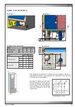
Gerät
Downflow
Upflow
181/221 251 181/221 251
Kühlwasser-
Eintrittsleitung
Ix
428
428
416
430
Iy
186
186
190
190
Iz
57
57
53
53
Kühlwasser-
Austrittsleitung
Ox
382
382
370
383
Oy
186
186
190
190
Oz
125
125
121
121
Oy/Iy
Ox
Iz
Ix
Oz
52
251
50
143
50
187
52
x
z
y
55 70 70
120 70
2 x 50
4 x 32
A
A
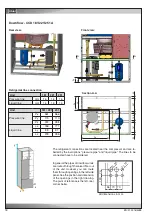
Downflow/Upflow - CCD/U 181/221/251 G
EN
To connect the piping notice the labels on the pipe ends.
Water pipe diameters
Rear view:
Rear view:
Section A-A
All dimensions in mm.
Unit
Inlet pipe
mm
Outlet pipe
mm
Unit
Cooling water
inlet pipe
Ix
Iy
Iz
Cooling water
outlet pipe
Ox
Oy
Oz
In general the pipes of downflow units
are routed through the raised floor out
of the unit. However you can route
them through openings in the left side
panel. See the position and dimension
of the openings in the right drawing.
The point of reference is the left, rear
corner below.
Summary of Contents for Mini-Space DX CCD131A
Page 13: ...07 2016 G20 13 EN 5 3 Dimensional drawings Cabinet size 1 Cabinet size 2...
Page 36: ......
Page 58: ...10 01 2017 air_MSDX 150 1000 810 700 160 920 EN Size 2 Filter top with flexible duct...
Page 62: ......
Page 66: ......
Page 70: ......
Page 73: ......

