28
/07.2016/
G20
EN
• Adjustment of the power switches according to electrical data sheet.
• Switch on the A/C unit at the master switch.
• Switch on the control-circuit fuses and the power switches of the fan and the
compressor in sequence.
• Close the electrical compartment door.
The controller is now supplied with power, so you can use it for adjustments.
Make sure that the heat rejecting system is operating.
A
- air-cooled condenser
G
- dry cooler
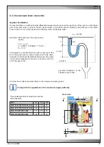
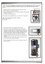
Switching on power switch
Do not turn the adjustment screw beyond the end of the calibrated scale range, as it may result
in overheating and short-circuit at the consumer or in the destruction of the power switch.
non-calibrated range
Controller C7000, Start/stop-key
• Adjust the desired return air temperature at the controller.
• Start the A/C unit by pressing the Start/Stop-key on the controller.
• Check after 20 minutes operation, whether bubbles are visible in the
sight glass of the liquid line. If this is the case, refrigerant might have
escaped by a leak. Check the circuit on leaks, eliminate these and top
up the circuit with R407C in regard of the chapter "Maintenance".
• Check the oil level at the compressor in respect of the right level.
The oil level should be between the lower quarter and the middle of the
sight glass.
• Check the current consumption of the compressors and the fans com-
paring it with the values of the technical data.
• Instruct the operational staff of the controller manipulation (refer to the
controller manual).
Oil level at the compressor
Summary of Contents for Mini-Space DX CCD131A
Page 13: ...07 2016 G20 13 EN 5 3 Dimensional drawings Cabinet size 1 Cabinet size 2...
Page 36: ......
Page 58: ...10 01 2017 air_MSDX 150 1000 810 700 160 920 EN Size 2 Filter top with flexible duct...
Page 62: ......
Page 66: ......
Page 70: ......
Page 73: ......


