/07.2016/
G20
31
EN
Compressor
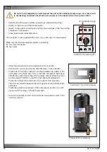
In the compressor there is an ester oil charge, which does not have to be renewed under normal operation conditions
and holds out for the unit's lifetime. However, it is possible that the ester oil, as it reacts hygroscopically, has taken
up humidity of the air after repeated recharging of the refrigerant circuit due to repair works. The interaction between
ester oil and water results in the formation of acid. Owing to a hyperacidity, corrosive processes take place inside
the compressor. In this case the ester oil should be exchanged.
The oil level can be checked by looking at the sight glass of the compressor.
Expansion valve
The refrigerant circuit is equipped with a expansion valve, which controls the superheating in the evaporator.The
superheating is adjusted to 7 K at the factory and may not be modified. The expansion valve can freeze, if the hu-
midity in the system is excessive.
Do not thaw by soldering flame, danger of explosion ! Thaw with moist warm cloth. Check the sight
glass.
8.4 Air circuit
Heat exchanger (Evaporator)
The heat exchanger consists of copper tubes with aluminium fins. If refrigerant leaks occur, they should be searched
for at the heat exchanger. Beyond that, the heat exchanger is exposed to the air pollution, the particles of which
settle at the fins and reduce the heat transmission the same as raise the air resistance. The latter shows when the
fan current increases.
The heat exchanger can be cleaned by pressurized air which has to be blown opposite to the normal air flow direction
along the fins.
Do not distort the fins while cleaning, this also increases the air resistance !
Fan
The bearings of the fans are lifetime lubricated and do not need maintenance. Check the operation current. An in-
creased operation current indicates a winding short circuit in the fan motor.
Air filter
A filter monitor controls the state of the filter. As soon as the pressure loss exceeds an adjustable value, a filter alarm
via the controller is released. The controller can be configured such as to compensate the pressure loss by a higher
fan speed, however you should not wait too long for exchanging the filter. In upflow units the filters can be accessed
by the front doors. In downflow units the filter lie on the evaporator and can be accessed from the top.
The clogged filter elements can not be cleaned with pressurized air, as the filter structure would be destroyed other-
wise. When you re-install the filter elements after the exchange, take care that the side with the coloured mark (dirt
side) is turned away from the heat exchanger.
Summary of Contents for Mini-Space DX CCD131A
Page 13: ...07 2016 G20 13 EN 5 3 Dimensional drawings Cabinet size 1 Cabinet size 2...
Page 36: ......
Page 58: ...10 01 2017 air_MSDX 150 1000 810 700 160 920 EN Size 2 Filter top with flexible duct...
Page 62: ......
Page 66: ......
Page 70: ......
Page 73: ......


