2
/11.2015/
raisedfloor
H
min
— H
max
X
Z
Y
Z (min. 50)
Z (min. 800)
Z
(min. 50)
H
min
—
H
max
[mm]
995 — 1045
895 — 945
795 — 845
695 — 745
595 — 645
495 — 545
355 — 405
270 — 320
EN
Angle Connection
Butt Joint
Cross Connection
Connecting the bars
(
View from below)
X/Y = Opening in raised floor
Z = Limit of distance
Minimum distances and mounting instructions
Raised floor stand
Recommended concrete
foundations
(no (floor) finish)
Mafund strips
Upper edge of
rough floor
Raised floor support
Raised floor stand
Continuous seal
Raised floor
Raised floor connection
for details, see next page
Hammer head screw M8 x 30
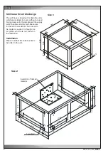
General design of the raised foor stand
Unit width
- Please observe that the floor stand must be decou-
pled from the surrounding floor plates by damping
insertions and that mafund plates are laid under the
floor supports.
- The raised floor cutting (notch) should at least be
15° and must not have any contact to the raised floor
stand, which could result in bone-conduction.
- If the floor stand is placed near a wall, a minimum
distance of 50 mm should be respected. The gap
between wall and floor stand should be closed by tin
stripes.
- The dimensions of the openings in the raised floor
(X and Y) are 10 mm longer than the raised floor
stand. The joint must be closed by customers with a
continuous seal.
- A concrete foundation is recommended in the area
of the raised floor supports.
- The raised floor supports have to be installed on
vibration dampening material (do not screw down the
supports!).
- Prior to installation of the A/C unit, the raised floor must
be installed 7 mm higher than the raised floor plates,
as the mafund plates are compressed by the weight of
the A/C unit.
Summary of Contents for Mini-Space DX CCD131A
Page 13: ...07 2016 G20 13 EN 5 3 Dimensional drawings Cabinet size 1 Cabinet size 2...
Page 36: ......
Page 58: ...10 01 2017 air_MSDX 150 1000 810 700 160 920 EN Size 2 Filter top with flexible duct...
Page 62: ......
Page 66: ......
Page 70: ......
Page 73: ......


