3
/11.2015/
raisedfloor
EN
Raised floor stand
Adjustable support plate
Adjusting nut
Support pipe
Support base
Mafund strips
Raised floor cut out angle
Continuous seal profile
Before unit installation
Raised floor plate
Angled bracket
Permanently elastic seal
Fixing
Sealing detail
when distance Z < 100 mm
Sealing detail
when distance Z > 100 mm
Detail of raised floor connection
1
2
3
4
5
6
7
8
9
10
11
12
13
Other mounting options (e.g. louvers)
If louvers shall be installed beneath the unit, these must be first mounted onto the adapter plate. If there are two or
three louvers, the louver shafts are connected by a coupling piece. The louver actuator, which has to be installed on
the shaft, will later be on the right unit side in the proximity of the electric cabinet.
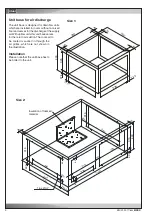
Positioning of the A/C unit on the floor stand
When positioning the A/C unit on the floor stand, it must be brought precisely into the correct position above the floor
stand from the front (under no circumstances diagonally). Hereby use mounting aids to bring in the unit and secure
these by fixing belts. We recommend further to lay in advance at least two securing instruments (e. g. square steel
bars) on the stand to avoid a slip-off.
When the unit is in the right position the securing aids can be taken away and the unit can be set down. Now the
mounting aids can be pulled away under the unit.
Mounting aid
Summary of Contents for Mini-Space DX CCD131A
Page 13: ...07 2016 G20 13 EN 5 3 Dimensional drawings Cabinet size 1 Cabinet size 2...
Page 36: ......
Page 58: ...10 01 2017 air_MSDX 150 1000 810 700 160 920 EN Size 2 Filter top with flexible duct...
Page 62: ......
Page 66: ......
Page 70: ......
Page 73: ......


