20
/07.2016/
G20
PS-
PS+
24V
Komponenten
CC.. 51 - 91 A
CC.. 131 - 151 A
CC.. 181 A
CC.. 221 - 251 A
Verdampfer
dm³
3,48
4,28
8,42
8,62
Sammler
dm³
1,5
1,5
5,3
5,3
EN
- Systems without refrigerant receiver or sight glass must always be filled according to weight.
- Systems with refrigerant receiver should be filled according to weight but can also be filled by checking the sight
glass.
If you use the refrigerant R407C, please note that R407C is a ternary blend. Take care that you add
refrigerant in a liquid state, as the ratio of the refrigerant components changes if one of the three
compounds passes over into the gaseous phase.
- Before the system is filled with refrigerant, it must be clean and dry inside. (Refer to evacuation instructions).
Then proceed as follows:
The standing refrigerant bottle is connected to the suction side via a pressure gauge station. The weight is noted
shortly before filling. The specified amount of refrigerant is now added when the system is operating. During
filling the pressure in the refrigerant bottle will adjust to that of the system. Filling is then no longer necessary.
This can be seen by the icing up of the bottle or by checking the pressure gauge. The bottle valve must then be
closed until a pressure increase has taken place which is above the suction pressure of the system. This pro-
cess can be accelerated if the bottle is wrapped in hot moist towels or it is placed in a water bath at a maximum
temperature of 50°C.
Never heat up the refrigerant bottle with a naked flame as there is a risk of explosion.
6.3.1.3 Filling the refrigerant circuit
Compressor
Condenser
Receiver
Safety valve
Solenoid valve
to expansions
valve
to evaporator
A/C unit
external installation
Non return
valve
Open stop
valves !
for cabinet
size 2 only
for cabinet
size 1 only
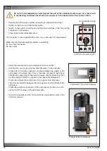
1. Solder the pipe ends of the external refrigerant piping coming from the aircooled condenser to the refrigerant pipe
connections of the A/C unit.
2. Connect a 24 V AC voltage or a permanent magnet at the solenoid valve in the liquid line in order to open the
valve. The closed solenoid valve would hamper an even dispersion of refrigerant during the filling.
3. Open the stop valve and in units of size 2 the Rotalock valve on the pressure side of the compressor.
4. The refrigerant circuit is filled with a nitrogene filling under a pressure of 2.5 to 5.0 bar. Evacuate the refrigerant
circuit by the Schrader valves until approximately 0 bar.
5. Fill the refrigerant circuit by the Schrader valves with refrigerant.
6. Disconnect the voltage from the solenoid valve or remove the permanent magnet.
Components
Evaporator
dm³
Liquid receiver
dm³
To estimate the required refrigerant charge in advance, consider following volumes:
Summary of Contents for Mini-Space DX CCD131A
Page 13: ...07 2016 G20 13 EN 5 3 Dimensional drawings Cabinet size 1 Cabinet size 2...
Page 36: ......
Page 58: ...10 01 2017 air_MSDX 150 1000 810 700 160 920 EN Size 2 Filter top with flexible duct...
Page 62: ......
Page 66: ......
Page 70: ......
Page 73: ......


