SB-7-632 Page 21
AEON PD Synthetic Lubricant should be drained after 6000 hours of operation. Re-fill with fresh AEON PD oil. If
mineral oil is used, perform the above oil change maintenance every 1500 hours. Recommended service
intervals are for normal blower operating conditions. Severe operating conditions may warrant more frequent oil
changes. Laboratory analysis of lubricant should be used to help determine the optimum oil change interval.
For best performance and equipment protection, use AEON PD Synthetic Lubricant, which has been specifically
formulated for positive displacement blowers. If you choose not to use AEON PD Synthetic Blower Lubricant,
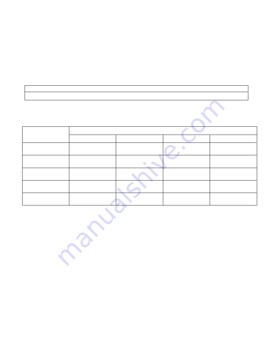
select an oil with rust and oxidation inhibitors, anti-foam additives, and the viscosities listed in FIGURE 3-5.
Do not use an oil that contains EP additives.
NOTICE
Flush the oil whenever a change is made from one type of oil to another.
Drain the current lubricant as thoroughly as possible. Refill with the new lubricant. Fill to normal level of the
blower, which is at the middle of the sight glass when the machine is not operating. Run the blower for one hour.
Shut off the blower and drain the lubricant completely. Refill the blower again with the new lubricant.
Blower
Discharge
Temperature
Ambient Temperature
Less than 10° F*
10° F to 32° F**
32° F to 90° F
Greater than 90° F
Less than 32° F
(0° C)
ISO 100
ISO 100
32° F to 100° F
(0° C to 38° C)
ISO 100
ISO 100
ISO 150
100° F to 225° F
(38° C to 105° C)
ISO 100
ISO 100
ISO 150
ISO 220
225° F to 300° F
(105° C to 149° C)
ISO 150
ISO 150
ISO 220
ISO 220
Greater than 300° F
(149° C)
***
***
*
For ambient temperatures less than 10° F, but not less than –20° F, the use of oil sump heaters, heated
enclosures or synthetic lubricant is required.
**
For ambient temperatures 10° F to 32° F, the use of oil sump heaters, heated enclosures or synthetic
lubricant is recommended.
***
The lubricant viscosity must be 70 SUS minimum at the lubricant operating temperature.
The pour point of the lubricant should be at least 5° to 10° F below the minimum expected ambient
temperature.
For continuous operation, where the lubricant temperature exceeds 200° F, synthetic lubricant is
recommended.
FIGURE 3-5 – LUBRICATION RECOMMENDATION
Summary of Contents for TANVAC HDV3000
Page 2: ...1300 998 784 STGGLOBAL NET OPERATORS MANUAL TANVAC HDV3000 Sec on 1 ...
Page 11: ...8 4 COMPONENT IDENTIFICATION Engine Control Panel Control Panel ...
Page 14: ...11 Water System Water pump Switch Water Pump ...
Page 15: ...12 Water Strainer Hose Reel ...
Page 16: ...13 Water Tank Drain Valve Lever Vacuum System Dump valve Suction Valve ...
Page 17: ...14 Blower Vacuum ...
Page 19: ...16 Primary Shutoff Assembly Collection Tank Interior Bag House Lid ...
Page 20: ...17 Bag House Drain Valve Tools Water Gun ...
Page 34: ...31 20 3000lt ELECTRIC CONTROL BOX CIRCUIT DIAGRAM 1 ...
Page 35: ...32 21 3000lt ELECTRIC CONTROL BOX CIRCUIT DIAGRAM 2 ...
Page 36: ...33 22 3000lt VACUUM UNIT BOTTOM RAIL ASSEMBLE ...
Page 37: ...1300 998 784 STGGLOBAL NET OPERATORS MANUAL Cat 2 2 Opera on Manual Sec on 2 ...
Page 137: ... Table 32 contd 100 SEBU8312 03 Reference Information Section Maintenance Log ...
Page 141: ......
Page 144: ...1300 998 784 STGGLOBAL NET OPERATORS MANUAL Comet Manual Sec on 3 ...
Page 161: ...1300 998 784 STGGLOBAL NET OPERATORS MANUAL Sutorbilt R Series Sec on 4 ...
Page 200: ...SB 7 632 Page 39 SECTION 8 PARTS LIST ...
Page 202: ...SB 7 632 Page 41 ...
Page 204: ...SB 7 632 Page 43 301GAE810 A Ref Drawing ...
Page 206: ...SB 7 632 Page 45 ...
Page 208: ...SB 7 632 Page 47 ...
Page 210: ...SB 7 632 Page 49 303GAE810 A Ref Drawing ...
Page 212: ...SB 7 632 Page 51 ...
Page 214: ...SB 7 632 Page 53 ...
Page 216: ...SB 7 632 Page 55 300GAE810 A Ref Drawing ...
Page 218: ...SB 7 632 Page 57 ...
Page 220: ...SB 7 632 Page 59 ...
Page 222: ...SB 7 632 Page 61 302GAA810 A Ref Drawing ...
Page 224: ...SB 7 623 Page 63 ...
Page 226: ...1300 998 784 STGGLOBAL NET OPERATORS MANUAL Sutorbilt P Series Sec on 5 ...
Page 245: ...SB 7 622 Page 12 1 PIPE STEEL 2 SCH 80 2 MED CARBON STEEL 1 2 FIGURE 9 GEAR DRIVER SK2150 ...
Page 258: ...SB 7 622 Page 25 SECTION 8 PARTS LIST 300GAF810 B Ref Drawing ...
Page 260: ...SB 7 622 Page 27 300GAG810 A Ref Drawing ...
Page 262: ...SB 7 622 Page 29 300GAH810 A Ref Drawing ...
Page 265: ......
Page 266: ...1300 998 784 STGGLOBAL NET OPERATORS MANUAL Lofa Manual Sec on 6 ...
Page 294: ...1300 998 784 STGGLOBAL NET OPERATORS MANUAL Excava on Hydro SWMS Sec on 7 ...
Page 314: ...1300 998 784 STGGLOBAL NET OPERATORS MANUAL Pressure Cleaner Water SWMS Sec on 8 ...


