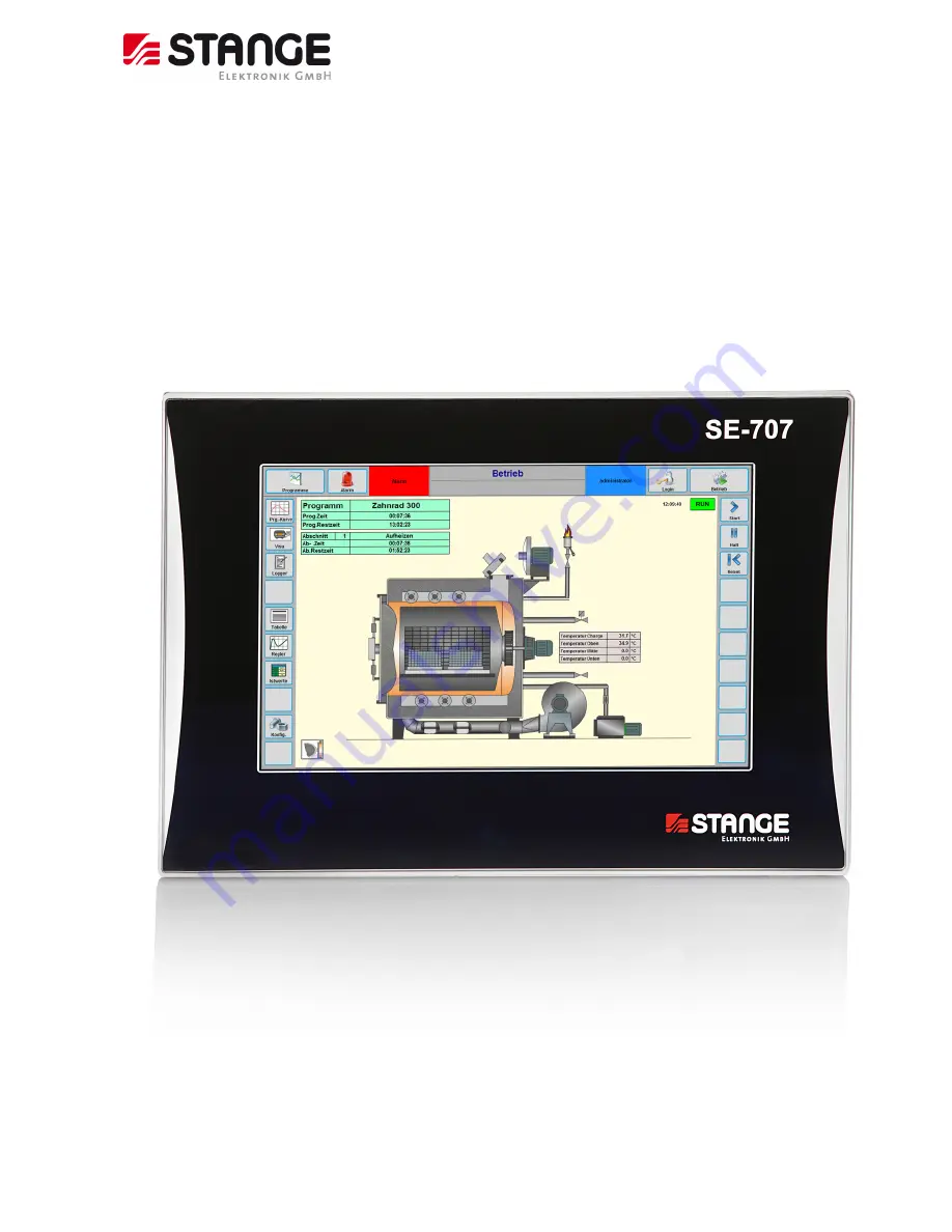
Program Controller SE-707
© 2018 by STANGE Elektronik GmbH
Subject to technical modifications
1
Operating Manual
Program Controller
SE-707
Documentation: October 2018
Page 1: ...Program Controller SE 707 2018 by STANGE Elektronik GmbH Subject to technical modifications 1 Operating Manual Program Controller SE 707 Documentation October 2018 ...
Page 2: ... 2 PACKING 12 3 3 STORAGE 12 4 TECHNICAL DATA 13 4 1 HARDWARE CHARACTERISTICS 13 4 2 SOFTWARE SPECIFICATIONS 15 4 3 FUNCTION BASIC DATA 16 5 INSTALLATION OF THE INDUSTRIAL CONTROL 18 5 1 GUIDELINES FOR THE INSTALLATION OF THE SE 707 18 5 2 GENERAL MOUNTING INSTRUCTIONS 18 5 3 INSTALLATION DIMENSION 19 5 4 INSTALLATION DEPTH 20 5 5 FRONT PANEL INSTALLATION 21 6 START UP 22 6 1 GUIDELINES FOR GROUND...
Page 3: ...anual 46 8 1 4 Program curve 46 8 1 5 Program jump 47 8 1 6 Automatic Program Start 47 8 1 7 Program change in actual segment 48 8 1 8 Editing of the operating program 48 8 1 9 Controller 49 8 1 10 Control Zone Detail View 49 8 1 11 PID Parameter 50 8 1 12 Control zone tolerance values limit values 51 8 1 13 Plant overview 51 8 1 14 Alarms 52 8 1 15 Alarm history 53 8 1 16 Process data actual valu...
Page 4: ...14 Process steps 143 8 3 3 15 Analogue multiplexers 144 8 3 3 16 BCD BIN Decoders 145 8 3 4 Special Functions 148 8 3 4 1 C Level Option 148 8 3 4 2 Humidity Calculation 152 8 3 4 3 Data Logger Option 153 8 3 4 4 Operating Hours Meter Option 163 8 3 5 User Administration 164 8 3 5 1 User 164 8 3 5 2 User Groups 165 8 3 5 3 Automatic user login 167 8 3 5 4 User Profile Modbus 167 8 3 6 Settings 168...
Page 5: ...r to avoid accidents damages to persons and physical damage WARNING This symbol marks dangers which result in impairment of health injuries lasting physical injury or to death as well as substantial property damage Keep the displayed references to the operational safety absolute exactly and behave in these cases particular carefully WARNING Danger by electric current This symbol makes attentive to...
Page 6: ...ns of the EU Directive 2014 30 EU electromagnetic compatibility Gummersbach 2018 06 25 P Jaspert Managing Director _________________________________ _________________________________ Place and Date of Issue Name authorized Signature The device was tested in a typical situation If modifications are made without our agreement this declaration loses its validity The device does not fall into the rang...
Page 7: ...k on and with the device in particular before the start up For damage and troubles which result from the non observance of the manual the manufacturer does not take over liability The manual is to be put aside and directly accessible with the device for all persons who work on or with the device The assignment of the manual to third party is not permitted and obligates if necessary to compensation...
Page 8: ...lar the use of the device for the control or as replacement of safeguarding equipment in the sense of the machine directive 98137 EG is not permitted Requirements of any kind against the manufacturer and or its authorized persons because of damage on the basis of not intended use of the device are excluded For all damages on the basis of not intended use the operator is responsible alone Among the...
Page 9: ...ase of unearthed operation 2 7 Responsibility of the operator The device may be operated only in technically perfect and safe condition Apart from the operational safety notes in this manual are to be considered and kept the generally valid safety regulations and regulations for the prevention of industrial accidents for the area of application of the device as well as the valid environmental regu...
Page 10: ... as recommended 2 9 Maintenance Battery The storage battery serves for the backup of the real time clock and the remanent PLC data With complete charge the storage battery has a holding time of approx 8 10 weeks In order to avoid data loss it should be paid attention to the fact that the device is switched off not longer than this time With completely empty storage battery a time of 48 hours opera...
Page 11: ...57939 Fax 49 0 2261 55212 E mail support stange elektronik de 2 14 Disposal STANGE units can be recycled Send back the device delivered free to STANE Elektronik GmbH for disposal Or contact a certified electronic waste disposal centre for environmentally acceptable recycling and disposal of your old devices Particularly to be considered is The device contains a lithium storage battery The device c...
Page 12: ...ble transport damage Note the damage on transportation document delivery note of the carrier Start reclamation Reclaim hidden damages immediately after recognizing at the latest within 8 days date of receipt in writing because claims for damages can be made valid only within the valid complaint periods 3 2 Packing For the transport of the device is to be used excluding the original packaging 3 3 S...
Page 13: ...densing Climate storage 20 60 C 10 90 relative humidity non condensing EMC interference resistance EN 61000 6 2 Interference radiation EN 61000 6 3 Power supply Voltage 24 V DC 18 30 V Voltage drops 10 ms according EN 61000 6 2 Reverse voltage protection Yes Fuse Solder fuse 2 A slow blow Electrical isolation Yes Current consumption Typ 500 mA at 24 VDC for 2 min after power on 750 mA Power consum...
Page 14: ...ntact potential free CAN CANopen fieldbus 9 pole SubminD connector electrically isolated USB 1 and 2 USB connection female for external storage medium USB Memory Stick Ethernet connector Ethernet 10 100 Mbit s RJ45 female connector Profibus DP optional Profibus DP Slave optional interface module 9 pole SubminD connector electrically isolated Processor core CPU Freescale i MX 6 ARM Random access me...
Page 15: ...isualization Ready made graphical user interface installation possibility of customer specific screen pages and or unit diagrams depending on stage of extension Administration of 8 operating levels user profiles Online language switching with Unicode language support Russian Chinese etc depending on stage of extension Control system ECS SE 707 are designed for STANGE ECS control system connection ...
Page 16: ...imum length 40 characters 40 characters User name 40 characters 40 characters Comment field 1024 characters 1024 characters I O s Digital inputs 200 64 Digital outputs 200 64 Number of actual values 48 16 Number of average value per actual value 50 50 Number of correction point per actual value 5 5 Free linearization pair of values 64 64 Number of analogue values 32 16 Maximum CAN node number 15 2...
Page 17: ...pages 5 2 Program graphics number of pins digital tracks 6 6 Program graphics digital tracks pages 11 6 PLC PLC instructions 3200 3200 Digital input variables 800 800 Digital output variables 800 800 PLC function inputs 1146 1146 PLC function outputs 1615 1615 Flag not zero voltage safe 256 256 Flag zero voltage safe 256 256 Comment text length only monolingual 50 characters 50 characters Data Log...
Page 18: ... supplied fixing frame and 2 securing nuts All SE 707 devices can be operated up to a maximum ambient temperature of 45 C The ambient temperature stated applies to the area in the direct vicinity of the lower connectors if the device is mounted vertically with unimpeded air convection and a maximum operating height of 2000 m above sea level The cooling slots must always be free in order to ensure ...
Page 19: ... modifications 19 5 3 Installation dimension Installation dimension SE 707 The device requires a mounting cut out of B x H 354 x 238 mm 0 5mm The thickness of the front panel may not exceed 7 mm For better sealing Use mounting frame rearwards 196 6 312 0 346 0 354 0 229 8 238 0 ...
Page 20: ...7 2018 by STANGE Elektronik GmbH 20 Subject to technical modifications 5 4 Installation depth Installation depth SE 707 The Installation depth for the SE 707 99 2 mm Length of the mounting clips 65 mm behind the mounting plate ...
Page 21: ...elivered mounting frame on the back side Place one of the enclosed clamps from the back on each side until the stroke is reached the recess in the metal plate of the clamp grips to a nipple on the side of the housing Turn the screw clockwise the device is pulled backwards and secured Installation diagram Holding clamps 354 mm 238 mm Mounting frame Minimum distance for side by side mounted devices ...
Page 22: ... cause electric shock or faulty operation of equipment Failure to disable all power to the SE 707 and related equipment during installation or removal procedures could result in death or serious injury to personnel and or damage to equipment Always follow appropriate safety precautions and ensure that power to the SE 707 is disabled before attempting to install or remove the SE 707 or related equi...
Page 23: ...bH Subject to technical modifications 23 6 2 Overview of the connections No Element 1 24 V DC power supply 24V PE GND 2 Alarm connector A1 A2 for Watchdog and alarm output 3 CAN connector 9 pol Sub D 4 USB 1 and 2 5 Ethernet RJ45 6 Option slot 6 1 4 5 2 3 ...
Page 24: ... the condition MEMORY RESET turn switch position 3 LED 2 CAN This LED gives information about the condition of CANopen field bus function LED flashes green The field bus is running all CAN slaves are online and no CAN slave configuration error is available LED flashes red CAN slaves not all online or CAN slave configuration error LED flashes red with 2 Hz BusOff Error LED off CAN interface inactiv...
Page 25: ... condition may be jumped over or not be recognized 6 2 3 System Watchdog 6 2 3 1 General The SE 707 device hardware has a hardware watchdog with an output as potential free semi conductor relay output lead through at a device connector If the Watchdog output is really evaluated depends on the discretion of the plant manufacturer 6 2 3 2 Mode of operation The Good state of the Watchdog output is a ...
Page 26: ... in case of device repair Further system events are for example device switching on and off turning the turn switch on the device rear side etc Note If a hardware defect is really existent it is not sure that such a system event entry could really be written to the file 6 2 4 The alarm relay 6 2 4 1 General At the back side of the SE 707 devices an alarm relay is lead through floating semi conduct...
Page 27: ...d carefully and with the right direction into the opening and be pressed as far as it will go with above mentioned screwdriver The card locks if the tool pressure is taken away Take care for the correct orientation of the medium The contact area is located to the device rear panel Attention Electrostatic discharges may destroy electronic components You must wear a grounded bracelet or if this is n...
Page 28: ...orrectly Connections for the SE 707 must comply with specific local regulations The connection must be made as follows 1 The cross section of the power supply cable must be at least 0 75 mm and a maximum of 2 5 mm 2 A flexible lead or wire can be used for the connection whereby the end should be equipped with a cable end sleeve 3 The current consumption must be taken into account when implementing...
Page 29: ...d shield braid by approx 3 cm 3 Turn back the braid over the cable sheath 4 Use a heat shrinkable tubing or rubber grommet to cover the exposed cable sheath with the folded back shield braid so that 5 to 8 mm of exposed cable shield is left at the sheath end and is cleanly covered at the back 5 Fit the connector 6 The cable is then fastened at the exposed shield braid and the cable sheath below it...
Page 30: ... a standard Ethernet cable 1 1 via a hub or directly using a crosslink cable The cables are also available as an accessory Before the device is connected to the Ethernet network the IP address of the device and the programming PC must be set IP addresses can be obtained from your system or network administrator IP addresses must be uniquely defined in an Ethernet network The IP address of all netw...
Page 31: ...selected in a wide range and only the standard CiA baud rates are implemented recommended 125kBaud max The SE 707 is the master on the CAN bus Connector Pin No Signal Description 1 2 CAN LOW Negative data signal 3 4 5 6 7 CAN HIGH Positive data signal 9pol 8 SubD 9 Case Case Cable shield The CAN interface is isolated The max Baud rate is 500kBit s Recommended setting 125kBit s The CAN terminating ...
Page 32: ...inimum delay between two points on the bus is 0 The maximum delay is determined by the bit timing and the delays of the sender and receiver circuits The figure shows the minimum wiring with shielding between two bus stations with the Sub D connector as an example A bus terminating resistor 220 Ohm between Pin 2 and Pin 7 must be connected at the beginning and the end of each CAN bus Do not swap ar...
Page 33: ... Yes Alarm 2 contact Open Open Closed Overview of the connections See chapter 6 2 6 9 Connection of the PROFIBUS DP Slave interface Option Please ensure that termination resistors are available at both ends of the cable If special PROFIBUS connectors are being used these resistors are often found inside the connector and must be switched on For baud rates above 1 5 MBaud use only special connector...
Page 34: ...linked to each other with repeaters there can be up to 127 devices on the network at maximum The maximum permissible cable length of a PROFIBUS segment depends on the baud rate used see the following table Baud rate in kBit s Max distance 9 6 1 200 m 19 2 1 200 m 93 75 1 200 m 187 5 1 200 m 500 400 m 1 500 200 m 3 000 100 m 6 000 100 m 12 000 100 m Table PROFIBUS Segment length in dependence of th...
Page 35: ...tential free RS 485 interface according to PROFIBUS Standard EN 50170 For the hardware connection no 90 or connectors with inclined outlet can be used Connectors with axial cable outlet need more space under the device Front view of netJACK with PROFIBUS DP System LED The subsequent table describes the meaning of the System LED of the system and the Profibus LED communication module LED Color Stat...
Page 36: ...g 5 Hz Communication to at least one Slave is disconnected Red On Communication to all Slaves is disconnected or another serious error has occurred Redundant Mode The active Master was not found Off Off Device is not switched on or supply voltage is missing Table LED states for the PROFIBUS DP Master protocol LEDs states Definition Blinking 5 Hz The indicator turns on and off with a frequency of 5...
Page 37: ... of the Real Time Ethernet interface of the communication module Figure Pinning of Ethernet connectors Pin Signal Description 1 TX Transmit Data 2 TX Transmit Data 3 RX Receive Data 4 TERM Bob Smith Termination 5 TERM 6 RX Receive Data 7 TERM Bob Smith Termination 8 TERM Table Ethernet interface channel 0 and channel 1 pin assignments Note Auto crossover function is supported by the netJACK module...
Page 38: ... Off Off No error Red Flashing 2 Hz No data exchange Red On No configuration or low speed physical link or no physical link LINK LED green Green On The device is linked to the Ethernet Off Off The device has no link to the Ethernet RX TX LED yellow Yellow Flickering load dependent The device sends receives Ethernet frames Off Off The device does not send receive Ethernet frames Table LED states fo...
Page 39: ...ngs of the PC for Ethernet communication 6 12 1 Separation of automation network and company office network Company office nets typically consist of computers that have usually also direct access to the Internet A separation of automation net and company office net is urgently advised Only in this way is ensured that the connection of automation devices among each other and or to the control syste...
Page 40: ...er systems with appropriate protocols e g Windows Peer to Peer is possible describes this chapter how the IP address is adapted exemplarily at the operating system WIN 7 6 12 4 Settings Windows 7 10 The net referred settings can be adapted like follows Windows Start Control Panel Network and Sharing Center Network and Sharing Center Change adapter settings In this window all active connections are...
Page 41: ...mple for a subnet mask 255 255 0 0 Windows 7 10 takes over changes without a restart 6 12 5 Settings of the IP address in the device By the delivered visualization application With the delivery of a SE 707 control a visualization application is installed which permits to adjust the IP address How the address has to be entered is explained in chapter Host Interface After the input of the IP address...
Page 42: ...st includes the following Memory test Flash disk test 7 2 Shutdown behaviour Voltage dips of 10ms at 24V are bridged by the power supply unit Longer voltage dips will cause the PLC to be reset automatically ATTENTION Writing data to the CompactFlash during a power supply failure will cause data loss The ECS EPAM visualization software therefore makes a copy of the file in the directory C BACKUP be...
Page 43: ... After switching on the tension the user program is loaded from the CompactFlash into the RAM and the PLC is started Procedure Power on PLC Programm present Battery o k Reset cold Start PLC INI PLC Status Run PLC Status Stop PLC Status System Fault PLC Status Power on Startup WARM Default Startup STOP Hardware o k No No No No ...
Page 44: ...debar allows calling additional functions and on the left sidebar is changed to other pages Note The unit operation depends on the configuration of the respective unit s and values Therefore the layout of the display can deviate This example shows however the basic operation of the SE 707 devices 8 1 Operation Warning If you do changes in OPERATING mode the changes immediately affect process opera...
Page 45: ...st the tabular representation Graphic presentation with the program curve is considered in the next chapter The following parameters are displayed in the overview Set value number digital track number Set value designation digital track designation State increasing constant decreasing manual auto error Actual value and or On and Off Dimension The Error state may result for digital tracks normally ...
Page 46: ... at configuration are also considered in manual operation 8 1 4 Program curve The program curve consists of set value curve upper graph and track view bottom graph Further set values and or tracks can be displayed by operating the corresponding button Left next to the set value curve and the track view is displayed which line colour corresponds to which value The actual value of the set value and ...
Page 47: ...Jump Set Value which should be entered with segment number The same input of a jump may result in different targets within the program with loops depending on actual position in program at the beginning in reset state right in the middle in any segment at the end of the program A jump to a segment within a program loop will cause the executing of the complete loop 8 1 6 Automatic Program Start A s...
Page 48: ...cations only if it is situated within a larger one In this case the inner loop takes over the new values when the outer one returns to start again 8 1 8 Editing of the operating program The operating program screen is reached by the left sidebar on the screen A program which is located in the operating memory can be tested and changed on the numeric operating data page with the same functions and ...
Page 49: ... operation only possible in the detail view A currently activated self optimization of any control zone Note is signalized by flashing of the column headline The following values are represented by selecting a control zone PID Parameter Xp proportional amplifying factor Tn integral re adjusting time Tv differential rate time Controller values limit value low high tolerance minus tolerance plus tol...
Page 50: ...er can be edited by touching the Xp Tn sec and Tv sec button The PID parameters can be determined self dependent over the program controller not possible for every type of controller by operating the Optim On and Optim off button An activated self optimisation is clarified by the abbreviation Optim in the status display and blinking headline WARNING A self optimization should always be made under ...
Page 51: ...ton Visu opens the plant overview screen This button is only available if a corresponding page was intended and programmed and the corresponding option was released In the plant overview a schematic picture or a plant photo are normally displayed It is possible to display programmer information and plant data An example of such a representation is displayed in the screenshot right The visualisatio...
Page 52: ...w displays the accumulated alarms Alarm number and alarm test are represented Furthermore is displayed when the alarm appeared disappeared and when he was acknowledged Further options Alarms System acknowledgement All alarms are acknowledged Horn Turn off horn if available Individual acknowledgement The marked alarm is acknowledged NOTE Appearing alarms are displayed by red highlighted text Alarm ...
Page 53: ...ed 8 1 16 Process data actual values Here the actual values are listed Changing the values is not possible The number depends on the device configuration Displayed values Actual value number Description Value Dimension State1 B in case of break detection in case of range overshooting in case of range undershooting 1 These three state messages may occur in combination Overvoltage at 0 10 V or overc...
Page 54: ...ues are listed The number of plus and minus tolerance values depends on the device configuration Changing the values is possible Change button if they were released in the configuration and the selected login level permits this Displayed values Tolerance number Description Dimension Set plus tolerance Set minus tolerance Actual deviation in case of overshooting the plus tolerance in case of unders...
Page 55: ... can be visualized and reset thereby on the control system level Operating Hours Meter Configuration 8 1 21 Data Logger Option The overview of the stored batch data is reached via Data Logger button This button is only available if the correspondent option is released The data logger function offers among other things the possibility to bring recorded lag data to display The diagram base settings ...
Page 56: ...djusted during log data recording for instance when switching from summer to winter time then this has no effect to stored log files Only alarms and the entry on the overview page at the end of recording consider a changed clock 8 1 22 Logger Graph Option Graphic representation of values Set Values Actual Values Time H Min Sec Displayed are starting time always 00 00 00 cursor time temporally posi...
Page 57: ...it option ON is activated in the logger configuration 8 1 24 Program start with data logger Option A corresponding window arrears at batch start if in the logger parameters were defined that batch description header data or comments should be editable at batch start A red cross is displayed next to the corresponding field if the input of data was defined as required Logger Parameter 8 1 25 Configu...
Page 58: ...ser rights belong to this code and displays the user name on the left side next to the Operation button after the user and the corresponding code was entered The user name is explained left next to the OPERATION button The register user is reset by operating the LogOff button The password of the actual registered user can be changed by means of the Change Password button Inputs for user and passwo...
Page 59: ... View Programmer Table X X X X Manual Set Value X X X View Operating Program X X X Change Operating Program X X X Operating Program Insert Copy Delete X X Alarms View alarm Overview X X X X X Acknowledge Alarm Horn X X X Acknowledge Alarm X View Alarm History X X X Delete Alarm History X Visualisation View Visualisation X X X X X Operate Visualisation X X X X Visu Button 1 X X X X X Visu Button 2 ...
Page 60: ...Controller Overview Manual Value X X Controller Overview Optimisation X Enter Controller Limit Values X X Enter Controller Tolerance Data Logger View Data Logger X X X X Data Logger General X X X X View Log Data X X X X Administrate Log Data X X X Import Log data X X Configure Logger Pins X X Process Start X Edit Batch Name X Edit Header Data X Edit Comment Text X ...
Page 61: ...ts Number of loops Total time Creation date Modification date State The program selection takes place by marking the corresponding program blue marked 8 2 2 Creating programs In order to create a new program select the New button on the right sidebar The program number is recommended in the following window Already occupied program numbers cannot be used Input a program name and confirm with OK Th...
Page 62: ...re considered i e tracks locked among each other cannot be switched on at the same time Definitions made in the configuration for digital tracks and set values free off on take over and or free locked are here considered too One process step is assigned to each segment Set values and digital tracks were already exactly defined in the configuration they have received a designation there and a relea...
Page 63: ...m must be selected blue highlighted in order to load one of the programs from the program memory to the operating mode Operate the O Prog button thereafter and the program is loaded to the operating mode after a security query The representation automatically changes to operation to the programmer Note The operating program cannot be loaded if a program is already running in the controller 8 2 7 S...
Page 64: ...MS ZIP with all program data is created loaded on the data medium thereby A description text 24 characters for program list identification can be entered At present it is not possible to change the name the comment as well as the directory for storage on data storage medium Note Data loss possible A possibly already existing older file PROGRAMS ZIP is overwritten on data medium during storing All ...
Page 65: ...program Each eight loops with max 9999 repetitions are available Loops may be nested but however not crossed A program may be 49 days long at maximum Incorrect inputs are red visualized Incorrect programs cannot be stored An appropriate window with the reference of the error cause appears ATTENTION If loops are programmed to be situated one in the other the smaller loop must be contained completel...
Page 66: ...configuration can disturb the operation of the device and can cause serious damage of the entire unit and personal injuries In the CONFIGURATION pre settings of the operating parameters are made Select the Configuration button on the OPERATION screen page in order to reach the configuration level The following configuration settings can be made by selecting the desired configuration menu and opera...
Page 67: ...he screensaver prevents the burning in of a permanent static screen the screen brightness can also be reduced in two steps in order to treat the display lighting with care and to save energy Function Input range Background brightness Value range 50 up to 100 Screensaver Screensaver active Yes No Time delay step 1 Minutes value range 0 up to 1440 Brightness step 1 value range 0 100 Time delay step ...
Page 68: ...e of DHCP Yes receive IP address from a server IP Address Device address in the IP network example 192 168 0 57 Subnet mask Subnet mask address for the use in the IP network example 255 255 0 0 Standard gateway Gateway address for use in the IP network Remote Client enabled Remote access via SE 7xx remote client Parameter No only a Local Host can connect with the Datalink Interface default Yes Por...
Page 69: ...guage During reading programs by the ECS Recipe Manager the program name is read corresponding to the set language If ECS writes programs to the device the program name is registered to all 4 language fields This avoids that only a default text exists in the actually not set languages If a program should be overwritten by ECS then texts in another language get lost thereby 8 3 1 4 Siemens Modbus C...
Page 70: ... changed here by selecting one of the available designs f The points Connection Data Server and Exit Application only appear when using the SE7xx Windows Client remote control software Connection Data Server Here the IP address of the device which should be connected can be set for the remote control software Exit Application Terminates the remote control ...
Page 71: ...es delivered before October 2012 with revision 3 0 Note corresponds to those of the SE 5xx devices Only 64 digital inputs 64 digital outputs 16 analogue inputs and 16 analogue outputs can be processed per CAN base at the same time The equipment of a single base is for example not allowed with three or four CAN E32 modules Two CAN E32 modules result altogether for one CAN base allowable 64 digital ...
Page 72: ...alogue output slot 1 Start number of analogue outputs in process image CAN base I O slot 1 Module type slot 2 Module type for CAN base I O slot 2 No digital input slot 2 Start number of digital inputs in process image CAN base I O slot 2 No digital output slot 2 Start number of digital outputs in process image CAN base I O slot No analogue input slot 2 Start number of analogue inputs in process im...
Page 73: ...e adapted according to requirements Data mapping Predefined data blocks Variable data mapping Number of input modules Only for variable data mapping Number of input modules from device point of view in the Profinet IO Controller this corresponds to the number of output modules Value range 0 10 For data mapping with predefined data blocks this value is constantly set to 9 Number of output modules O...
Page 74: ...ping Assignment of input modules from device point of view for Profinet IO Controller this corresponds to the output modules Data Designation in the Device Description Value Range Description Description of input definition max 24 characters A description can be entered optionally here however for the interface function it is not necessary Target range Digital inputs Mapping 1 bit per value Digita...
Page 75: ...e Controller set value Mapping 4 Byte Real per value Lower limit of range Mapping 4 Byte Real per value Upper limit of range Mapping 4 Byte Real per value Controller minus tolerance Mapping 4 Byte Real per value Controller plus tolerance Mapping 4 Byte Real per value Limit value Mapping 4 Byte Real per value Plus tolerance Mapping 4 Byte Real per value Minus tolerance Mapping 4 Byte Real per value...
Page 76: ...evice Description value range DP slave address Profibus address of the device 1 125 Number of digital input blocks Number of digital input blocks each with 64 Bit 0 5 Number of digital output blocks Number of digital output blocks each with 64 Bit 0 5 Number of analogue input blocks Number of analogue input blocks 16 Bit with sign 0 40 Number of analogue output blocks Number of analogue output blo...
Page 77: ...9E15 default setting 1 0 Adjustment offset 9 99999E15 9 99999E15 default setting 0 0 DP Slave Analog Ausgangswerte Data name in the device Description value range Description Description for the analogue output value max 24 characters Source range Set value Actual value Formula value Variable value Manipulated variable Manipulated variable heating controller A Manipulated variable cooling controll...
Page 78: ...range reacting time of the system FMS provides a large number of high performance application functions Data exchange takes place acyclic on request of the process PROFIBUS DP is suitable especially for automated manufacturing DP is a cost effective alternative for parallel wiring between PLC and remote peripherals It is designed for quick data exchange on the sensor actor level Here central contr...
Page 79: ... peripherals by means of the transfer media This system configuration ensures the shortest bus cycle time Figure 2 PROFIBUS DP mono master system In case of multi master operation several master devices are connected by one bus They are either sub systems independently from one another each consisting of one DPM1 and the corresponding DP slaves or additional projecting and diagnosis devices see fi...
Page 80: ...2 DPM2 Devices of this type are devices for programming projecting or operating purposes They are used for start up in order to build up the DP system configuration or for unit control in running operation DP slave A DP slave is a peripheral device I Os drives HMI valves which receives input information and transmits output information to the peripherals There are also applicable instruments which...
Page 81: ...erefore the bus cycle time must be shorter than the program cycle time of the master The master transmits an initializing telegram containing the output data for the DP slave After having accepted this initializing telegram the DP slave answers immediately with a response telegram with input data transferred to the master Communication with the NetJack module is realized with the master slave meth...
Page 82: ...er is represented in figure 6 with an exemplary configuration with 64 digital inputs 64 digital outputs 2 analogue inputs and 2 analogue outputs Figure 5 Process image structure Profibus DP Master e g S7 CPU315 2DP Profibus DP Slave DualPort RAM S7 configuration SE configuration EW 7 EW 9 EW 11 EW 13 AW 5 AW 7 AW 9 AW 11 PEW 256 PEW 258 PAW 256 PAW 258 Digital outputs DO 64 bit 7 14 Digital inputs...
Page 83: ...nput and output bytes like already mentioned The assignment between the channels of the input and output modules and the bits and bytes of the process image is realized by the NetJack module The leading PLC manufacturers offer a project planning software for PROFIBUS DP system projecting in order to generate parameter data for the master in an easy manner This open projecting is based upon electro...
Page 84: ...rag and drop in the SINEC L2 net correspondingly Assign the slave to the desired station address After that take the desired DP_SLAVE modules out of the hardware catalogue and place them by drag and drop according to NetJack module configuration in the structure list of the slave Therein the DP_SLAVE modules must be listed in the following order see configuration examples All digital inputs All di...
Page 85: ...ith double click on the projected slave the properties of the slave Figure 7 are displayed and the physical assignment between the plug in places of the input and output channels and the addresses in the PLC Figure 8 Figure 7 Properties of the DP slave Figure 8 Physical assignment of the DP slave ...
Page 86: ...and analogue inputs outputs Overview of digital and analogue I O s Digital inputs Digital outputs Actual values Analogue outputs Free linearization curves The corresponding settings can be reached by marking a line in the list and then operating the Edit button Functions for digital and analogue inputs outputs Function Input Range Parameter Number Digital inputs Number of digital inputs Max 24 cha...
Page 87: ...99 Free linearization curve 2 3 9999 9999 9999 9999 Range code Input range in case of linear signal 0 10 Volt 0 20 mA 4 0 mA Actual value function None C in F convert actual value scaling 1 actual value scaling with limit 1 Display format Actual value display format according to format enumeration Low range limit Input range 9 99999E15 to 9 99999E15 High range limit Input range 9 99999E15 to 9 999...
Page 88: ...lue one function output is assigned to which is activated dependently on a configurable error condition see also Table AV 2 Parameter 17 In this case the Actual Value Defective alarm message 209 is put out Possible malfunction causes are actual value range underflow or overflow and or sensor break In case of an defective actual value the output behaviour can be configured see also table Actual val...
Page 89: ...c actual values come in like the STANGE CAN periphery because measured values are thrown away If values come in e g over the Profibus Slave module the actual value would deviate from the actually value of the Profibus Master if this values sends only during change of value and not cyclically Average value calculation By means of the average value calculation the actual value can be smoothed A slid...
Page 90: ...ltering A comparison of the filtered measuring values e g for thermocouple or Pt100 measuring sensors can be executed with the help of the actual value correction For each actual value up to 5 correction point are freely definable After the input of the number of correction points the actual value correction point input and the definition of the correction values takes place Analogue input signal ...
Page 91: ...g Value 900 displayed after the last correction point are based on the resulting equation of a line of the last two correction points in the example P4 and P5 Thus results the correction value 5 5 P1400 for the expected temperature range end value of 1400 C in the example Example calculation m slope Δy Δ correction value P1400 correction value at 1400 C Δx Δ AVMeasuring value P1400 3 m Δx 0 005 14...
Page 92: ...esults a value of 3 Fig 3 resulting correction value curve of 2 correction points Specifics In case of only one released correction point a parallel shift of the actual value curve takes place application e g for temperature offset In case of two correction values at the same measuring point the first value available in the table is used It is checked whether the correction points are located with...
Page 93: ...l operation 950 ms for fast operation 95 ms If CAN modules for thermocouple and standard signals CAN IW4 XL and CAN IW8 XL are used with the remote peripherals then one standard signal actual value per input module can be measured favoured faster The measuring rate for fast operation amounts 400 ms for an IWx XL module ATTENTION Only one standard signal channel per module may be configured fast in...
Page 94: ...ameter Number Number of analogue outputs Description Analogue output name max 24 Unicode characters Function code Unassigned Set value Actual value Formula value Variable value Manipulated variable Manipulated variable Heating Manipulated variable Cooling Controller actual value Controller set value Function number Number of the selected operand in Function Code Output functions Normal Invers Scal...
Page 95: ...r cent value 0 100 however in case of CAN slave circuits in the I O system it is transferred as a real value Example A setpoint value of 0 1200 C is transferred in a CAN slave circuit as a real value with a range of 0 1200 ATTENTION If scaling is executed the manner of the value provided to be scaled for DAC modules real value for CAN slave must be taken into account when defining scaling factor a...
Page 96: ...E15 to 9 99999E15 Output Output value input range 9 99999E15 to 9 99999E15 Free Linearization Curves Functional description With the actual value processing in the device there can be performed linearization for all conventional thermocouples and Pt100 For other types of actual value sensors two linearization curves can be freely defined see CONFIGURATION Actual Values Each curve can obtain up to ...
Page 97: ...ly to the four curve points the smallest and the largest possible value x must be specified In the present example the input values 0 V and 2 V equal output values are assigned to The same applies to the input values 8 V and 10 V To define the pictured linearization curve therefore six pairs of values are required The range configured for the appurtenant actual value see CONFIGURATION Actual Value...
Page 98: ...igned to each segment Functions for each set value Function Input Range Parameter Number Set value number Description Max 24 Unicode characters Display format Max 10 Unicode characters Lower limit of range Set value lower limit input range 9 99999E15 to 9 99999E15 Upper limit of range Set value upper limit input range 9 99999E15 to 9 99999E15 Dimension text Set values display format according to f...
Page 99: ...Furthermore a process step is assigned to each segment see CONFIGURATION Process Steps Control Inputs The device obtains seven impulse inputs impulse length 200 msec minimum and two static inputs Reset Re set program to start values impulse input Start Program start from the beginning from RESET or END status program continuation from STOP status impulse input Stop Program stop from RUN status imp...
Page 100: ... Av Sv of the jump Jump to Program End By activating this control input positive edge in RUN or STOP status an immediate jump to program end is executed Status Outputs The program status is issued by means of one of the seven outputs RESET Program on start values RUN Program running STOP Program stop also active in case of power failure stop segment end stop and interlocking stop END Program on en...
Page 101: ...ontrol zones Overview of the control zones Control zone number Description Controller type A Controller type B Dimension The functions are defined over the Edit button The numbers of parameters are defined by operating the PARAM button on the left side bar Functions for each control zone Function Input Range Parameter Number Number of control zones Description Control zone name 24 Unicode characte...
Page 102: ...l fixed value Y manual fixed value only for Y manual code fixed value Inverse Y Inverse mode of action No normal yes invers Y Scaling Y Min A 0 0 up to 100 0 only for PID A Y Scaling Y Max A 0 0 up to 100 0 only for PID A Y Scaling Y Min B 0 0 up to 100 0 only for PID B Y Scaling Y Max B 0 0 up to 100 0 only for PID B Cycle time A seconds Minimum cycle time A 1 999 Sec only for 2 point PID A 3 Cyc...
Page 103: ...ctual value Limit value LOW MAN Substitute AUTO actual value selected Control zone ON OFF Overview Configuration of a Standard Control Zone Alternatively Configuration of Control Zone 1 Configure actual value for Control Zone 1 Configure setpoint value for Control Zone 1 Configuration of the controller outputs by means of the internal PLC function e g for a 2 point PID controller Heating cooling f...
Page 104: ...simulated ever more easily by means of ON OFF cycle ratios An opto switching output for Heating and Cooling is provided for each control zone In Heating cooling mode with 2 point PID controllers a 3 point PID controller is available switching between Heating and Cooling being controlled by means of a switching interval split range operation NOTE All explications for the heating cooling operation m...
Page 105: ... of the motor position the potentiometer value can be fed back via any actual value Parameter 30 however it is used only for displaying If the X tracking function should be used a potentiometer actual value is necessary ATTENTION Y hysteresis must be matched to motor inertia The 3 point stepping controller operates with a scan rate of 0 1 sec i e the smallest step is an impulse of 0 1 sec If the m...
Page 106: ...r Cooling are switched on switching distance positive The changeover of PID parameters between heating and cooling takes place automatically The working point of a pure P controller is positioned exactly between heating and cooling Instead of linear PID controllers for heating and cooling can be used also 2 point PID controllers Beside the analogue outputs digital signals are outputted thereby as ...
Page 107: ...prevents the divisor Av 3 for gas quantity from being 0 be cause otherwise the formula cannot be calculated In normal calculation processes this constant C 2 has no perceptible effect AV 2 AV 3 air quantity gas quantity The X1 formula value is applied as substitute actual value to the air gas relation control zone SV 2 Regulation of gas quantity Regulation of air quantity Motor for air shutter cou...
Page 108: ...d in configuration by entering four values Example see adjacent figure Setpoint value range 0 1400 C Y minimum 20 Y maximum 100 Setp value at Y min 400 C Setp value at Y max 1000 C Y limitation must be activated by means of a separate external function input FI 49 68 for each control zone specific program sections can therefore be run without Y limitation Switching in of Y limitation can be effect...
Page 109: ... MANUAL of the Y output and input a manual value is possible independent from this function input Y MANUAL Mode For each control zone there exists an static function input Y MANUAL constant value FI 122 124 126 As long as this function input is active the manipulated variable Y of the controller is forced to manual operation and the following the Y Manual Code configuration the manipulated variabl...
Page 110: ...nced by this function Y Scaling The range of the manipulated output is limited by a scaling The Manipulated Variable Y can be scaled limited for each control zone with parameters Scaling Y Min and Scaling Y Max The scaling is always active in manual operation Activation via separate function input is not necessary Example see adjacent figures Controller linear PID Y Min 10 Y Max 80 A valid permiss...
Page 111: ... In case of taking over a device configuration of the 4th or 5th generation has to be paid attention Note that the SE 707 controller scan rate of all control zones is set fixed to 0 1 seconds For the older devices the scan rate could be set variable between 0 1 and 1 0 seconds task tables X Tracking For X tracking the controller setpoint value is equated to the actual controller actual value by me...
Page 112: ...ly can be configured as well parameter 45 progression factor max Hereby is accelerated the rise of the beginning of the x Tracking ramp in case of large set actual difference The maximum value for parameter 45 is 5 0 i e the gradient is raised maximally to the fivefold value dependent on the size of the x Tracking difference The default setting for progression factor min is 1 0 i e no gradient cha...
Page 113: ...or running time 0 100 There exists one function input Start Y tracking impulse of 200 msec minimum FI 1121 and one function output Y tracking active FO 1281 for each control zone Y tracking cannot be activated if the control zone is switched off Function Inputs 0025 0044 PID control zone OFF ON The potentiometer actual values are continuously actualized in the memory of the instrument Additionally...
Page 114: ...he controller reacts Parameter Adjustment Control process interference behaviour Start up behaviour setpoint value jump Xp Larger Higher damping interferences are stabilized slowlier Slower diminution of Y energy excess contingently overshooting Smaller Slighter damping interferences are stabilized faster in case of oscillating Y enlarge Xp Faster diminution of Y relative energy with oscillating a...
Page 115: ...section is unknown and if it is possible to set the control loop into an instable status for a short time the control parameters can be determined by setting Xp 0 Tn 0000 sec Tv 000 0 sec Now the control loop oscillates around the setpoint value X Legend Act value T oscillation length x oscillation amplitude x Xn controller range e g 0 1400 C T see also the following table Time t Settings for the ...
Page 116: ...Tn Tg Tv 0 5 x Tn PI Xp 2 9 x F Tn 1 2 x Tg 0 Parameters automatically determined are registered under the just selected parameter set Tg x t Yn Time t Legend Yn Manip Variable range Y Manipulated variable Tu Delay time Tg Compensation time Tg t x Xmax x Xmax Maxim value of controlled system Xn Adjustment range of the controller in the dimension of X actual value Example If a Y modification of 10 ...
Page 117: ...aller Xp in order to reduce the overshooting Redundant Actual Value Processing for controllers In addition to the controller actual value a redundant actual value processing can take place by means of two replacement actual values The target of this redundancy is to ensure the function of the unit even in case of single actual values loss by a plausibility check In order to make this possible must...
Page 118: ... the remaining actual value is used to control A tolerance monitoring makes no sense a switching to replacement actual value takes not place The function outputs actual value break the defective actual values FO1 48 are set If all three actual values are defective then a switching to replacement actual value takes place if this was configured Otherwise the averaged actual value from the defective ...
Page 119: ... 1 Add actual value 2 Add actual value Actual value used for control FO AV break controller actual value FO AV break add actual value 1 FO AV break add actual value 2 FO AV break replacement actual value FO 989 actual value break FO 990 tolerance alarm 500 505 450 502 5 OFF OFF OFF OFF OFF 500 520 450 510 0 OFF OFF OFF OFF ON Break 505 450 505 0 ON OFF OFF OFF OFF Break Break 450 450 0 ON ON OFF O...
Page 120: ...possible warm up time Afterwards the hold phase begins usually with a break in the set value process Through this break it comes to a strong temperature overshooting and the controller hardly tries to reduce this overshooting again particularly because of today s very well isolated furnaces The method of resolution is here a soft interception of the set value rise before reaching the hold phase Fo...
Page 121: ...aph displays the regulation of two disturbances in the hold phase It can be seen that the X tracking is retriggered in each case Configuration notes see below Configuration in the device The following configuration points were created for the two examples above When the X tracking is released must then only be defined in the PLC statement list Control zones e g Function Input X tracking time base ...
Page 122: ...esignation 24 Unicode characters max Tolerance code 1 comparison and or operand 1 minuend Inactive Actual value Av set value Sv Actual value Av actual value Av Formula value X set value Sv Actual value Av formula value X Formula value X formula value X Actual value Av targetAv Formula value X targetAv Set value Sv targetAv Tolerance code 2 is needed additionally as subtrahend for the following val...
Page 123: ...ulated variable Y Manipulated variable heating Yh Manipulated variable cooling Yc Controller actual value RA Controller set value RS External activation Yes No Display format 0 0 00000 E 0 log10 Plus tolerance 0 999999 Minus tolerance 999999 0 Actual values AV Function output Set values SV plus tolerance overshot Formula values X Target set value TargetSv Funct input tolerance release Function out...
Page 124: ...yes In this case a change of tolerance values in the configuration remains without impact A tolerance buffer is created in the program memory The tolerances can be edited via corresponding display page or a connected computer Request of the target set value With the help of a tolerance it is possible to determine whether an actual value or formula value or set value is located next to the target s...
Page 125: ...rameter Number Number of limit values Limit values Read Write Release for changes in OPERATION yes no Criteria for each limit value Function Input Range Designation 24 characters max Limit value type No limit value Set value Sv Actual value Av Formula value Xv Variable value Va Manipulated variable Y Manipulated variable heating Yh Manipulated variable cooling Yc Controller actual value RI Control...
Page 126: ... No hysteresis standard setting on manufacturer s works 0001 9999 Over limit value Monitoring for limit value undershooting Limit values function mode Actual value C Actual value dependent limit value with negative hysteresis monitoring for overshooting 1 Limit value outp 0 Actual value C Actual value dependent limit value with positive hysteresis monitoring for undershooting 1 Limit value outp 0 ...
Page 127: ...r Segment Time or Remaining Segment Time With the aid of the internal PLC there can be realized requests concerning the actual segment time or the remaining segment time When the program is active RUN or STOP status the appurtenant function output is activated as soon as a limit value has exceeded or fallen short of The limit value must be configured accordingly and defined in full seconds Example...
Page 128: ...rms Alarm code Alarm input mode 1 1 1 1 and BCD 1 1 and BIN Alarm ackn code Alarm acknowledge code General single and general single Delay time priority 1 8 Delay time for alarm priority 1 8 0 1 9999 9 seconds Criteria for each alarm Function Input Range Description Alarm text 100 characters max Priority Alarm inactive Alarm priority 1 to 8 Delay time alternative Alternative alarm delay time secon...
Page 129: ...owledge acoustic signal acoustic signal off All alarm inputs can be assigned a delay time linked to the priority or an individual delay time An alarm is registered only once the delay time has elapsed Coded Alarm Processing BCD binary Additionally to direct alarm selection 1 1 an alarm number can also be transmitted BCD or binary coded FIs 507 508 and 513 522 as well as FO 411 Coded activation mus...
Page 130: ...tage and or current input values 210 Battery empty Voltage of the battery too low Device was not switched on for a long time Let device switched on for 48 hours In case of repeated appearance Exchange of the battery Service Fa STANGE 212 CANbus alarm No data transfer between SE 707 and CAN basis and or SIOS node s or configuration problem of the hardware configuration 1 Data line interrupted 2 CAN...
Page 131: ...ourable 1 Delete no longer needed batch data manually 2 Configure automatic deletion of batches 3 Configure alarm limits for this warning 226 Data logger no storage space The storage space for the data logger is used up Further data are NO longer stored 1 The maximum possible 200 batches are reached now 2 The memory card is full now 1 Delete no longer needed batch files manually 2 Configure automa...
Page 132: ...E15 to 9 99999E15 Dimension text 10 characters max External release PLC FI external release FI 826 830 Always active External release static External release pos flank Reset Code PLC FI formula reset FI 825 829 Formula value 0 0 Formula value set value Sv Formula value actual value Av Formula value formula value Xv Formula value variable value Va Formula value constant value C Reset Code Operand N...
Page 133: ...nd division first then addition and subtraction A formula reset makes a formula value change to a defined value A constant value but also a process value can be used as reset value The SE 707 formula processing considers multiplication and division first then addition and subtraction ATTENTION This was not the case for the previous device generation SE 4xx SE 5xx Constant values can be used for di...
Page 134: ...ion in and outputs Assignment between digital in outputs and function inputs outputs Predetermined from user and changeable Assignment between flags digital and function inputs outputs In the PLC program statement list NOTE Function outputs should not be changed with PLC commands because the function modules output results are biased Exceptions FO 425 552 PC control system outputs Writing can be r...
Page 135: ...ed and its number or value with the numerical keys Functions for each operand Operand SPS Operand Code Parameter I Direct input from the CAN peripherals O Direct output to the hardware peripherals F Flag for intermediate data not zero voltage safe F Flag for intermediate data zero voltage safe FI Function inputs of the function modules 1 FO Function outputs of the function modules 1 CMS Definition...
Page 136: ... 0003 L I 0002 I2 O1 0004 R O 0001 Caused by the sequential action of the PLC a change of dominance can be effected by alternation of Line 1 2 and Line 3 4 Example 3 RS flip flop With without Low voltage Protection The Flags 257 512 are low voltage protected FF1 low voltage protected 0001 L I 0001 0002 S F 0257 I1 0003 L I 0002 0004 R F 0257 I2 F257 FF2 not low voltage protected 0001 L I 0001 0002...
Page 137: ... I 0004 I4 0017 R TI 0003 Example 5 Pulse generator with fixed pulse pause ratio e g lamp flash rate 1 Hz 0001 L E 5 0002 S TP 4 0003 L Cms 500 same time for pause and pulse 0004 L TP 4 flash rate 0005 O 4 output The pulse generator from example 5 starts with the pulse time Example 6 Pulse generator with variable pulse pause ratio e g lamp flashing 1 Hz 0001 LN TI 6 0002 S TN 5 0003 L Cms 700 Paus...
Page 138: ... A signal alternation is detected with the XO linkage of Command 0002 and filtered off with Command 0003 at a change from 0 to 1 Flag 2 as a pulse edge flag can be inquired at any place in the PLC program If Command 0003 is replaced by A F 0001 the logic reaction occurs at Input 1 alternating from 1 to 0 negative edge A logic reaction is effected only for a signal alternation of at least 100 msec ...
Page 139: ... PID Parameter Set 5 0018 R FI 0161 for Zone 5 0019 R FI 0162 Temperature 5 C 0020 S FI 0163 0021 L FO 0173 Select PID Parameter Set 6 0022 S FI 0161 for Zone 6 0023 R FI 0162 Temperature 15 C 0024 S FI 0163 0025 L FO 0174 Select PID Parameter Set 7 0026 R FI 0161 for Zone 7 0027 S FI 0162 Temperature 25 C 0028 S FI 0163 0029 L FO 0175 Select PID Parameter Set 8 0030 S FI 0161 for Zone 8 0031 S FI...
Page 140: ...s in CONFIGURATION depends on the variable display format which has been chosen here If this is modified the ranges must be re entered too From a control system or the visualization page read write access to the memory of variables is possible in any format In the control system the variables are mapped in an address range of 4500 4699 NOTE The content of variables is kept conserved in case of a p...
Page 141: ...imit Input range 2147483648 to 2147483647 UInteger16 lower limit Unsigned integer variables lower limit Input range 0 to 65535 UInteger16 upper limit Unsigned integer variables upper limit Input range 0 to 65535 Float lower limit Real variables lower limit Input range 9 99999E15 to 9 99999E15 Float upper limit Real variables upper limit Input range 9 99999E15 to 9 99999E15 Control system address M...
Page 142: ... input which is interlocked against another already switched on track this is rejected with an error message The action is not possible at present Functions for each digital track Function Input Range Parameter Number Number of digital tracks Description Digital track name 24 Unicode characters Manuel values at program load Delete not delete Delete Always set on Auto at program load Not delete Pos...
Page 143: ... value input is then needless and not allowed For digital tracks exists the possibility on the one hand to allow an input digital track release release or if this should not be allowed to pre set the appropriate digital track to On Off or Take over digital track release On Off Take over Functions for each process step Function Input Range Parameter Number Number of process step Description Process...
Page 144: ... Analogue value 2 Analogue value 3 Output value variable n Analogue value 4 2 1 e g FE 0906 20 e g FE 0905 Selection input FI 0905 0908 0 0 Analogue value 1 interconnected to output 0 1 Analogue value 2 interconnected to output 1 0 Analogue value 3 interconnected to output 1 1 Analogue value 4 interconnected to output Functions for each analogue multiplexer Function Input Range Parameter Number Nu...
Page 145: ...cess step No Program No Time only BCD Date only BCD Program time only BCD Process time only BCD Program remaining time only BCD Segment time only BCD Segment remaining time only BCD Set value Sv Actual value Av Formula value Xv Variable value Va Manipulated variable Y Manipulated variable Heating Yh Manipulated variable cooling Yc Controller actual value CA Controller set value CS Value number Num...
Page 146: ...2007 8 FO 2008 1 FO 2009 2 Hundreds FO2010 4 digit FO 2011 8 FO 2012 Sign bit 0 positive value 1 negative value the sign bit always follows up to the most significant bit Binary rate and separate sign Example 10 bits assignment starting with FO 2020 FO 2020 1 FO 2021 2 FO 2022 4 FO 2023 8 FO 2024 16 Value between FO 2025 32 0 and 1023 FO 2026 64 FO 2027 128 FO 2028 256 FO 2029 512 FO 2030 Sign bit...
Page 147: ...1 negative value the sign bit always follows up to the most significant bit 1 from n 32 max Example 16 bits assignment starting with FO 2060 FO 2060 1 if value 1 FO 2061 1 if value 2 FO 2062 1 if value 3 FO 2063 1 if value 4 FO 2064 1 if value 5 FO 2065 1 if value 6 FO 2066 1 if value 7 Only one bit is always set FO 2067 1 if value 8 FO 2068 1 if value 9 If the value ranges outside the coded FO 20...
Page 148: ...licence entry in the device license file C SE_SYST LIC The SE 707can be used for tempering work pieces in connection with a heat treatment furnace Temperature and furnace atmosphere are controlled by using a special formula for carbon calculation Inputs for temperature CO CO2 and O2 Consideration of correction values Choice between endogas and direct gassing Calculation example O2 formula CO 20 T ...
Page 149: ...NGE Elektronik GmbH Subject to technical modifications 149 Up to two C level calculations can be made in parallel the mode of operation of the C level calculation can be best viewed in the following graph Function block C level calculation ...
Page 150: ...at upper limit 35 0 Control system address 4500 Control system address 4502 Initialization mode None Initialization mode None Variable 3 O2 probe in mV Variable 4 Temperature in C Designation text Oxygen Designation text Temperature Dimension text mV Dimension text C Variable type IEEE Float Variable type IEEE Float Display format 0 Display format 0 Float lower limit 1000 Float lower limit 700 Flo...
Page 151: ...dershooting 9 FO 1 Soot limit reached 10 FO 1 CO2 undershooting 11 FO 1 CO2 overshooting 12 FO Reserve 13 FO Reserve 14 FO 0 O2 formula 1 CO2 formula 15 FO C level calculation disturbed 16 FO C level calculation active Actual value number CO Number of actual value which value is used as CO actual value If here none actual value is defined then the imputable variable is permanently used and the CO ...
Page 152: ...is taken as a basis for the calculation Criteria for humidity calculation Function Entry Range Parameter Number Number 0 2 Description 16 Unicode characters Variables No rel Humidity Number of variables 1 80 in which the relative humidity 0 100 should be archived none humidity calculation switched off Actual value No Dry Number of actual values 1 48 which value is used as dry air temperature C Act...
Page 153: ...y files An evaluation of recorded data is possible in different ways Display of logged data local at device with graphic representation Import to the PC program ECS Batchimport as well as further evaluation Important note about SD card medium Only industrial SD media checked and released by STANGE may be used Otherwise reliable log data storage cannot be ensured Obviously there are considerable di...
Page 154: ...rs a process start event in the logger Precondition is that either FO1311 or FO1305 are active this locking is already integrated fixed and must be considered for the design of the PLC trigger logic for generating a positive flank at FI967 The PLC is registered as user in this case because of creating the signal Note An actual user can only be assigned at start via device operation and or the remo...
Page 155: ...FO1305 goes back to logic 0 i e the data logger is active again Function input FI962 is dominant related to FI961 for active FI962 no start of a batch recording is possible FI963 Batch reset positive edge and or continuous signal This signal deletes the running log data recording FI1305 goes to logic 0 Function input FI963 is dominant related to FI961 and FI962 for active FI963 no start of a batch...
Page 156: ...ize of log files reaches and or exceeds the configured limit values No data got lost yet it is a warning notice that the log data must be deleted from the log data archive after possibly external archiving FO1313 Log data archive full error This function output goes to logic 1 if the number of archived log files and or the total size of log data reach the maximum possible limit values A loss of lo...
Page 157: ...Program Controller SE 707 2018 by STANGE Elektronik GmbH Subject to technical modifications 157 Operating page Process Start Process start flow chart ...
Page 158: ...grammer start takes place after 5 seconds in this example in order to clarify that the data recording may also contain a possibly preparation phase for the real program start L FO 1311 If process start triggered by start button A FO 1305 and if batch recording is active S TN 1 then after 5 seconds L CS 5 L TN 1 FI 809 Start of the programmer Take back process start as soon as the programmer is act...
Page 159: ...relation to parameter Alarm limit log data storage is to be considered Delete Logfiles count limit Number of listed LogFiles in directory from which is tried to delete Range 20 198 The relation to parameter Alarm limit number of log files is to be considered Batch info Edit before batch start Batch description editing before batch start Yes No or required Batch Info Edit allowed while batch is run...
Page 160: ...r Log Values The settings for log values are set by calling the corresponding menu and operating the Edit button Criteria for the log values Data naming in the device Description value range Description Header data name 24 Unicode characters text stored in 4 languages Value Type Log value type Unassigned i e the value is not taken over to the log data recording Set value Actual value Formula value...
Page 161: ...ariable Y heating Manipulated variable Y cooling Controller actual value Controller set value Text variable Value No Number of the operand selected in Value Type Dim Header data dimension 10 Unicode characters text stored in 4 languages Display format Header data display format only for numeric data Text length Header data text length only for text data Range lower limit Header data range lower li...
Page 162: ...t by calling the corresponding menu and operating the Edit button Criteria for the Log data Overview Data naming in the device Description value range Width Pixel Column width in pixels Value type Value identifier Consecutive Line number of the list Status Batch description Start time End time Program No Program name File name Header data field 1 Header data field 2 Header data field 20 Alignment ...
Page 163: ...for meter reset can be provided with a limit value output the limit value is specified in the configuration thereby can be provided with 24 characters long text all meters are deleted with the deletion of the RAM memory hardware test have control system addresses starting 4200 R W Float Criteria for each operating hours meter Function Input Range Description Operating hours meter name 24 Unicode c...
Page 164: ...n an initial password to a new created user which can be changed later In case of threefold wrong password input an alarm entry is created Several users can simultaneously access to one device Once locally at screen and at the same time via remote also The user administration logs which user have logged on and logged off at what time The user interface automatically logs on as guest when switching...
Page 165: ...embership The following user data sets are created for a new device by default System administrator plant manufacturer administrator Master master Foreman shift foreman foreman Plant operator operator Guest guest Functions for each Profile There is a selection for all configuration points Invisible inactive active Function Input Range Description User profile name 24 Unicode characters Configurati...
Page 166: ...ange values insert copy delete segments copy operating program in program archive Import program Import program Export program Export program Process Data View process data View quit process data process data button back button View process data AV LV TOL FV View process data actual values limit values tolerances formula values Change limit values Change limit values must be released in the config...
Page 167: ...Acknowledge Alarm Horn Invisible Inactive Activated Acknowledge Alarm Invisible Inactive Activated Delete Alarm History Invisible Inactive Activated Select Operating Program Invisible Inactive Activated Change Limit Values Invisible Inactive Activated Change Tolerances Invisible Inactive Activated Change Variable Value Invisible Inactive Activated Change Configuration AV Correction Invisible Inact...
Page 168: ...on then the clock is advanced one hour If this parameter is switched off then the clock is put back one hour An automatic switching between daylight saving time and standard time may create inconsistent data in the data logger For this reason exists an automatic switching between standard and daylight saving time Always check the clock time one more time after time zone offset and daylight saving ...
Page 169: ...ngs The configuration page of the program graph enables the colour assignment for the following elements Chart Settings Set Values Tracks The colour assignment for background X axis grid segment segment marking colour and time pointer line is made in the Chart Settings The settings can be adapted in the colour selection window by marking the desired element and operating the Enter button It is pos...
Page 170: ...nal to this parameters are stored as explicit files on the flash disk in case of special situations e g if the configuration is stored on an USB for backup purposes In this way the before mentioned device settings can be transferred problem free to another device The device parameters are likewise saved during a software update as files because in some cases it might be that the parameters from th...
Page 171: ...1 Mbyte With the help of a PC and the program SE7 PLC Editor a PLC statement list created with the program ECS Konf can be transferred to the device as alternative for import The PLC list must be opened in ECS Konf for this purpose and the required PLC lines marked and copied by means of the SE 7 PLC Editor to the Windows clipboard copy and paste into the SE7 PLC Editor A detailed description how ...
Page 172: ... USB stick Copy the ZIP file of the update package 1 1 to the folder without extracting it There may only be one of such a file in this folder because there is no further dialogue for file selection For a license update one suitable license file must be located somewhere on the USB stick Up to 3 folder levels are considered for the file search There may be several license files in different direct...
Page 173: ...levant for connections to a control computer ECS InTouch etc and to the SE 7xx Windows Client remote control software The IP address is only displayed in the SE 707 device In case of a remote control via a SE 7xx Windows Client this point is faded out 8 3 9 2 Software information On the Software Information screen page the following information are displayed Windows CE Version Server version GUI D...
Page 174: ...Control zones 8 20 Set values 8 30 Control tracks 32 64 Program number 99 250 Formula 8 20 Actual value inputs 16 48 Analogue outputs 16 32 Digital inputs 64 200 Digital outputs 64 200 Tolerance bands 16 40 Limit values 16 40 Alarms 64 200 CAN nodes 2 15 Analogue value multiplexer 5 10 8 3 9 4 Device health Information about the CPU temperature is displayed on the Devise Health screen page 8 3 9 5...
Page 175: ...3 Controller 51 Copy programs 64 Copyright protection 8 Creating programs 63 D Data logger Option 57 Data Logger Option 156 Date Time 171 Delete programs 65 Device Health 177 Device Information 176 Digital and analogue inputs outputs 89 Digital In Outputs 177 Digital tracks 145 Digital Variables 143 Dimension 14 Display 14 Display screen 70 Disposal 12 E Editing of the operating program 50 Electro...
Page 176: ...3 PE connection 10 PID Parameter 52 Plant overview 53 PLC Statement List 137 Power supply 14 Process data 55 56 Process steps 146 PROFIBUS Function Description 81 PROFIBUS DP Slave interface Option 34 PROFINET IO Device Slave interface Option 38 Program 63 Program change in actual segment 50 Program curve 48 Program Graph Pen Settings 172 Program jump 49 Program operation 63 Program overview 63 Pr...
Page 177: ...s 177 System Watchdog 26 T Technical data 14 Technical Support 12 Tolerance values 56 Tolerances 125 Transport 11 13 Transport inspection 13 U Unearthed operation 10 User 167 User Administration 167 User Groups 168 User interface 73 User Profile Modbus 170 W Weight 14 Wiring instructions 33 ...
Page 178: ... CAN peripherals 15 Control zone No for jump to actual value 6 Data logger 15 Digital input variables 15 Formula 13 PC control system inputs 10 PID control parameter selection 5 PID control zone OFF ON 3 Program number BCD 10 Programmer control inputs 13 Release tolerance 6 Substitute actual value activation 4 Substitute setpoint value activation 3 X tracking 15 Y AUTO MAN 4 Y limitation 3 Y MAN c...
Page 179: ...SE 7xx REFERENCE LISTS Function Inputs FI 2 ...
Page 180: ...4 0053 1103 04 1652 Control Zone 05 0054 1103 05 1653 Control Zone 06 0055 1103 06 1654 Control Zone 07 0056 1103 07 1655 Control Zone 08 0057 1103 08 1656 Control Zone 09 0058 1103 09 1657 Control Zone 10 0059 1103 10 1658 Control Zone 11 0060 1103 11 1659 Control Zone 12 0061 1103 12 1660 Control Zone 13 0062 1103 13 1661 Control Zone 14 0063 1103 14 1662 Control Zone 15 0064 1103 15 1663 Contro...
Page 181: ...ne 01 20 0125 1107 12 1724 Control Zone 03 Y AUTO MAN 0126 1107 13 1725 Y MAN constant value 0127 1107 14 1726 Control Zone 04 Y AUTO MAN 0128 1107 15 1727 Y MAN constant value 0129 1108 00 1728 Control Zone 05 Y AUTO MAN 0130 1108 01 1729 Y MAN constant value 0131 1108 02 1730 Control Zone 06 Y AUTO MAN 0132 1108 03 1731 Y MAN constant value 0133 1108 04 1732 Control Zone 07 Y AUTO MAN 0134 1108 ...
Page 182: ...79 Value 21 2 0181 1111 04 1780 Value 22 4 0182 1111 05 1781 Control Zone 08 Value 20 1 0183 1111 06 1782 Value 21 2 0184 1111 07 1783 Value 2 2 4 0185 1111 08 1784 Control Zone 09 Value 20 1 0186 1111 09 1785 Value 2 1 2 0187 1111 10 1786 Value 22 4 0188 1111 11 1787 Control Zone 10 Value 20 1 0189 1111 12 1788 Value 21 2 0190 1111 13 1789 Value 2 2 4 0191 1111 14 1790 Control Zone 11 Value 20 1 ...
Page 183: ...13 0278 1117 05 1877 Tolerance 14 0279 1117 06 1878 Tolerance 15 0280 1117 07 1879 Tolerance 16 0281 1117 08 1880 Tolerance 17 0282 1117 09 1881 Tolerance 18 0283 1117 10 1882 Tolerance 19 0284 1117 11 1883 Tolerance 20 0285 1117 12 1884 Tolerance 21 0286 1117 13 1885 Tolerance 22 0287 1117 14 1886 Tolerance 23 0288 1117 15 1887 Tolerance 24 0289 1118 00 1888 Tolerance 25 0290 1118 01 1889 Toleran...
Page 184: ...1 00 1936 Alarm Input 033 0338 1121 01 1937 Alarm Input 034 0339 1121 02 1938 Alarm Input 035 0340 1121 03 1939 Alarm Input 036 0341 1121 04 1940 Alarm Input 037 0342 1121 05 1941 Alarm Input 038 0343 1121 06 1942 Alarm Input 039 0344 1121 07 1943 Alarm Input 040 0345 1121 08 1944 Alarm Input 041 0346 1121 09 1945 Alarm Input 042 0347 1121 10 1946 Alarm Input 043 0348 1121 11 1947 Alarm Input 044 ...
Page 185: ...4 12 1996 Alarm Input 093 0398 1124 13 1997 Alarm Input 094 0399 1124 14 1998 Alarm Input 095 0400 1124 15 1999 Alarm Input 096 0401 1125 00 2000 Alarm Input 097 0402 1125 01 2001 Alarm Input 098 0403 1125 02 2002 Alarm Input 099 0404 1125 03 2003 Alarm Input 100 0405 1125 04 2004 Alarm Input 101 0406 1125 05 2005 Alarm Input 102 0407 1125 06 2006 Alarm Input 103 0408 1125 07 2007 Alarm Input 104 ...
Page 186: ...8 08 2056 Alarm Input 153 0458 1128 09 2057 Alarm Input 154 0459 1128 10 2058 Alarm Input 155 0460 1128 11 2059 Alarm Input 156 0461 1128 12 2060 Alarm Input 157 0462 1128 13 2061 Alarm Input 158 0463 1128 14 2062 Alarm Input 159 0464 1128 15 2063 Alarm Input 160 0465 1129 00 2064 Alarm Input 161 0466 1129 01 2065 Alarm Input 162 0467 1129 02 2066 Alarm Input 163 0468 1129 03 2067 Alarm Input 164 ...
Page 187: ... ones 2 binary 21 0515 1132 02 2114 BCD ones 4 binary 22 0516 1132 03 2115 BCD ones 8 binary 23 0517 1132 04 2116 BCD tens 1 binary 2 4 0518 1132 05 2117 BCD tens 2 binary 25 0519 1132 06 2118 BCD tens 4 binary 2 6 0520 1132 07 2119 BCD tens 8 binary 27 0521 1132 08 2120 BCD hundreds 1 0522 1132 09 2121 BCD hundreds 2 Alarm display 0528 1132 15 2127 Merge in alarm page automatically impulse i e ac...
Page 188: ... 14 5150 Control System Input 031 0584 1321 15 5151 Control System Input 032 0585 1322 00 5152 Control System Input 033 0586 1322 01 5153 Control System Input 034 0587 1322 02 5154 Control System Input 035 0588 1322 03 5155 Control System Input 036 0589 1322 04 5156 Control System Input 037 0590 1322 05 5157 Control System Input 038 0591 1322 06 5158 Control System Input 039 0592 1322 07 5159 Cont...
Page 189: ... 10 5210 Control System Input 091 0644 1325 11 5211 Control System Input 092 0645 1325 12 5212 Control System Input 093 0646 1325 13 5213 Control System Input 094 0647 1325 14 5214 Control System Input 095 0648 1325 15 5215 Control System Input 096 0649 1326 00 5216 Control System Input 097 0650 1326 01 5217 Control System Input 098 0651 1326 02 5218 Control System Input 099 0652 1326 03 5219 Cont...
Page 190: ...24 Formula 01 Reset 0826 1151 09 2425 Enable Formula 01 20 0827 1151 10 2426 0828 1151 11 2427 0829 1151 12 2428 Formula 02 Reset 0830 1151 13 2429 Enable 0831 1151 14 2430 0832 1151 15 2431 0833 1152 00 2432 Formula 03 Reset 0834 1152 01 2433 Enable 0835 1152 02 2434 0836 1152 03 2435 0837 1152 04 2436 Formula 04 Reset 0838 1152 05 2437 Enable 0839 1152 06 2438 0840 1152 07 2439 0841 1152 08 2440...
Page 191: ...Enable 0895 1155 14 2494 0896 1155 15 2495 0897 1156 00 2496 Formula 19 Reset 0898 1156 01 2497 Enable 0899 1156 02 2498 0900 1156 03 2499 0901 1156 04 2500 Formula 20 Reset 0902 1156 05 2501 Enable 0903 1156 06 2502 0904 1156 07 2503 Analog multiplexer selection 0905 1156 08 2504 Multiplexer 01 Input 0 20 0906 1156 09 2505 Input 1 2 1 Multiplexer 01 10 0907 1156 10 2506 Multiplexer 02 Input 0 20 ...
Page 192: ...gger 17 994 1162 01 2593 Header data trigger 18 995 1162 02 2594 Header data trigger 19 996 1162 03 2595 Header data trigger 20 X tracking 1097 1168 08 2696 Control Zone 01 1098 1168 09 2697 Control Zone 02 Control Zone 01 20 1099 1168 10 2698 Control Zone 03 1100 1168 11 2699 Control Zone 04 1101 1168 12 2700 Control Zone 05 1102 1168 13 2701 Control Zone 06 1103 1168 14 2702 Control Zone 07 1104...
Page 193: ...l Input Variable 011 2011 1500 11 8011 Digital Input Variable 012 2012 1500 12 8012 Digital Input Variable 013 2013 1500 13 8013 Digital Input Variable 014 2014 1500 14 8014 Digital Input Variable 015 2015 1500 15 8015 Digital Input Variable 016 2016 1501 00 8016 Digital Input Variable 017 2017 1501 01 8017 Digital Input Variable 018 2018 1501 02 8018 Digital Input Variable 019 2019 1501 03 8019 D...
Page 194: ... Digital Input Variable 069 2069 1504 05 8069 Digital Input Variable 070 2070 1504 06 8070 Digital Input Variable 071 2071 1504 07 8071 Digital Input Variable 072 2072 1504 08 8072 Digital Input Variable 073 2073 1504 09 8073 Digital Input Variable 074 2074 1504 10 8074 Digital Input Variable 075 2075 1504 11 8075 Digital Input Variable 076 2076 1504 12 8076 Digital Input Variable 077 2077 1504 13...
Page 195: ... Digital Input Variable 129 2129 1508 01 8129 Digital Input Variable 130 2130 1508 02 8130 Digital Input Variable 131 2131 1508 03 8131 Digital Input Variable 132 2132 1508 04 8132 Digital Input Variable 133 2133 1508 05 8133 Digital Input Variable 134 2134 1508 06 8134 Digital Input Variable 135 2135 1508 07 8135 Digital Input Variable 136 2136 1508 08 8136 Digital Input Variable 137 2137 1508 09...
Page 196: ... Digital Input Variable 189 2189 1511 13 8189 Digital Input Variable 190 2190 1511 14 8190 Digital Input Variable 191 2191 1511 15 8191 Digital Input Variable 192 2192 1512 00 8192 Digital Input Variable 193 2193 1512 01 8193 Digital Input Variable 194 2194 1512 02 8194 Digital Input Variable 195 2195 1512 03 8195 Digital Input Variable 196 2196 1512 04 8196 Digital Input Variable 197 2197 1512 05...
Page 197: ... Digital Input Variable 249 2249 1515 09 8249 Digital Input Variable 250 2250 1515 10 8250 Digital Input Variable 251 2251 1515 11 8251 Digital Input Variable 252 2252 1515 12 8252 Digital Input Variable 253 2253 1515 13 8253 Digital Input Variable 254 2254 1515 14 8254 Digital Input Variable 255 2255 1515 15 8255 Digital Input Variable 256 2256 1516 00 8256 Digital Input Variable 257 2257 1516 01...
Page 198: ... Digital Input Variable 309 2309 1519 05 8309 Digital Input Variable 310 2310 1519 06 8310 Digital Input Variable 311 2311 1519 07 8311 Digital Input Variable 312 2312 1519 08 8312 Digital Input Variable 313 2313 1519 09 8313 Digital Input Variable 314 2314 1519 10 8314 Digital Input Variable 315 2315 1519 11 8315 Digital Input Variable 316 2316 1519 12 8316 Digital Input Variable 317 2317 1519 13...
Page 199: ... Digital Input Variable 369 2369 1523 01 8369 Digital Input Variable 370 2370 1523 02 8370 Digital Input Variable 371 2371 1523 03 8371 Digital Input Variable 372 2372 1523 04 8372 Digital Input Variable 373 2373 1523 05 8373 Digital Input Variable 374 2374 1523 06 8374 Digital Input Variable 375 2375 1523 07 8375 Digital Input Variable 376 2376 1523 08 8376 Digital Input Variable 377 2377 1523 09...
Page 200: ... Digital Input Variable 429 2429 1526 13 8429 Digital Input Variable 430 2430 1526 14 8430 Digital Input Variable 431 2431 1526 15 8431 Digital Input Variable 432 2432 1527 00 8432 Digital Input Variable 433 2433 1527 01 8433 Digital Input Variable 434 2434 1527 02 8434 Digital Input Variable 435 2435 1527 03 8435 Digital Input Variable 436 2436 1527 04 8436 Digital Input Variable 437 2437 1527 05...
Page 201: ... Digital Input Variable 489 2489 1530 09 8489 Digital Input Variable 490 2490 1530 10 8490 Digital Input Variable 491 2491 1530 11 8491 Digital Input Variable 492 2492 1530 12 8492 Digital Input Variable 493 2493 1530 13 8493 Digital Input Variable 494 2494 1530 14 8494 Digital Input Variable 495 2495 1530 15 8495 Digital Input Variable 496 2496 1531 00 8496 Digital Input Variable 497 2497 1531 01...
Page 202: ... Digital Input Variable 549 2549 1534 05 8549 Digital Input Variable 550 2550 1534 06 8550 Digital Input Variable 551 2551 1534 07 8551 Digital Input Variable 552 2552 1534 08 8552 Digital Input Variable 553 2553 1534 09 8553 Digital Input Variable 554 2554 1534 10 8554 Digital Input Variable 555 2555 1534 11 8555 Digital Input Variable 556 2556 1534 12 8556 Digital Input Variable 557 2557 1534 13...
Page 203: ... Digital Input Variable 609 2609 1538 01 8609 Digital Input Variable 610 2610 1538 02 8610 Digital Input Variable 611 2611 1538 03 8611 Digital Input Variable 612 2612 1538 04 8612 Digital Input Variable 613 2613 1538 05 8613 Digital Input Variable 614 2614 1538 06 8614 Digital Input Variable 615 2615 1538 07 8615 Digital Input Variable 616 2616 1538 08 8616 Digital Input Variable 617 2617 1538 09...
Page 204: ... Digital Input Variable 669 2669 1541 13 8669 Digital Input Variable 670 2670 1541 14 8670 Digital Input Variable 671 2671 1541 15 8671 Digital Input Variable 672 2672 1542 00 8672 Digital Input Variable 673 2673 1542 01 8673 Digital Input Variable 674 2674 1542 02 8674 Digital Input Variable 675 2675 1542 03 8675 Digital Input Variable 676 2676 1542 04 8676 Digital Input Variable 677 2677 1542 05...
Page 205: ... Digital Input Variable 729 2729 1545 09 8729 Digital Input Variable 730 2730 1545 10 8730 Digital Input Variable 731 2731 1545 11 8731 Digital Input Variable 732 2732 1545 12 8732 Digital Input Variable 733 2733 1545 13 8733 Digital Input Variable 734 2734 1545 14 8734 Digital Input Variable 735 2735 1545 15 8735 Digital Input Variable 736 2736 1546 00 8736 Digital Input Variable 737 2737 1546 01...
Page 206: ... Digital Input Variable 778 2778 1548 10 8778 Digital Input Variable 779 2779 1548 11 8779 Digital Input Variable 780 2780 1548 12 8780 Digital Input Variable 781 2781 1548 13 8781 Digital Input Variable 782 2782 1548 14 8782 Digital Input Variable 783 2783 1548 15 8783 Digital Input Variable 784 2784 1549 00 8784 Digital Input Variable 785 2785 1549 01 8785 Digital Input Variable 786 2786 1549 02...
Page 207: ...l zone tolerances and limit values 17 Data logger 22 Digital Output Variables 25 Formula 14 Hilscher NetJack 1 25 Host Interface control system interface 20 Limit value outputs 5 Login Level local user 20 Manual setpoint value active 22 Manual Y active 21 Operation status 25 PC control system outputs 10 Process steps 13 Program number BCD 20 Programmer 13 Programmer Digital tracks 12 Programmer St...
Page 208: ...SE 7xx REFERENCE LISTS Function Outputs FO 2 ...
Page 209: ...01 10 3226 Actual Value 27 defective 0028 1201 11 3227 Actual Value 28 defective 0029 1201 12 3228 Actual Value 29 defective 0030 1201 13 3229 Actual Value 30 defective 0031 1201 14 3230 Actual Value 31 defective 0032 1201 15 3231 Actual Value 32 defective 0033 1202 00 3232 Actual Value 33 defective 0034 1202 01 3233 Actual Value 34 defective 0035 1202 02 3234 Actual Value 35 defective 0036 1202 0...
Page 210: ...05 04 3284 Control Zone 19 Output 1 0086 1205 05 3285 Output 2 0087 1205 06 3286 Control Zone 20 Output 1 0088 1205 07 3287 Output 2 Tolerances over undershooting 0089 1205 08 3288 Tolerance 01 Overshot 0090 1205 09 3289 Undershot Tolerance 01 40 0091 1205 10 3290 Tolerance 02 Overshot 0092 1205 11 3291 Undershot 0093 1205 12 3292 Tolerance 03 Overshot 0094 1205 13 3293 Undershot 0095 1205 14 3294...
Page 211: ... 0144 1208 15 3343 Undershot 0145 1209 00 3344 Tolerance 29 Overshot 0146 1209 01 3345 Undershot 0147 1209 02 3346 Tolerance 30 Overshot 0148 1209 03 3347 Undershot 0149 1209 04 3348 Tolerance 31 Overshot 0150 1209 05 3349 Undershot 0151 1209 06 3350 Tolerance 32 Overshot 0152 1209 07 3351 Undershot 0153 1209 08 3352 Tolerance 33 Overshot 0154 1209 09 3353 Undershot 0155 1209 10 3354 Tolerance 34 ...
Page 212: ... 0204 1212 11 3403 Limit Value 36 0205 1212 12 3404 Limit Value 37 0206 1212 13 3405 Limit Value 38 0207 1212 14 3406 Limit Value 39 0208 1212 15 3407 Limit Value 40 Alarms error message 0209 1213 00 3408 Alarm Output 001 0210 1213 01 3409 Alarm Output 002 Alarm 001 200 0211 1213 02 3410 Alarm Output 003 0212 1213 03 3411 Alarm Output 004 0213 1213 04 3412 Alarm Output 005 0214 1213 05 3413 Alarm ...
Page 213: ...3461 Alarm Output 054 0263 1216 06 3462 Alarm Output 055 0264 1216 07 3463 Alarm Output 056 0265 1216 08 3464 Alarm Output 057 0266 1216 09 3465 Alarm Output 058 0267 1216 10 3466 Alarm Output 059 0268 1216 11 3467 Alarm Output 060 0269 1216 12 3468 Alarm Output 061 0270 1216 13 3469 Alarm Output 062 0271 1216 14 3470 Alarm Output 063 0272 1216 15 3471 Alarm Output 064 0273 1217 00 3472 Alarm Outp...
Page 214: ...3521 Alarm Output 114 0323 1220 02 3522 Alarm Output 115 0324 1220 03 3523 Alarm Output 116 0325 1220 04 3524 Alarm Output 117 0326 1220 05 3525 Alarm Output 118 0327 1220 06 3526 Alarm Output 119 0328 1220 07 3527 Alarm Output 120 0329 1220 08 3528 Alarm Output 121 0330 1220 09 3529 Alarm Output 122 0331 1220 10 3530 Alarm Output 123 0332 1220 11 3531 Alarm Output 124 0333 1220 12 3532 Alarm Outp...
Page 215: ...3 15 3583 Alarm Output 176 0385 1224 00 3584 Alarm Output 177 0386 1224 01 3585 Alarm Output 178 0387 1224 02 3586 Alarm Output 179 0388 1224 03 3587 Alarm Output 180 0389 1224 04 3588 Alarm Output 181 0390 1224 05 3589 Alarm Output 182 0391 1224 06 3590 Alarm Output 183 0392 1224 07 3591 Alarm Output 184 0393 1224 08 3592 Alarm Output 185 0394 1224 09 3593 Alarm Output 186 0395 1224 10 3594 Alarm...
Page 216: ...443 1331 02 5298 Control System Output 019 0444 1331 03 5299 Control System Output 020 0445 1331 04 5300 Control System Output 021 0446 1331 05 5301 Control System Output 022 0447 1331 06 5302 Control System Output 023 0448 1331 07 5303 Control System Output 024 0449 1331 08 5304 Control System Output 025 0450 1331 09 5305 Control System Output 026 0451 1331 10 5306 Control System Output 027 0452 ...
Page 217: ...5356 Control System Output 077 0502 1334 13 5357 Control System Output 078 0503 1334 14 5358 Control System Output 079 0504 1334 15 5359 Control System Output 080 0505 1335 00 5360 Control System Output 081 0506 1335 01 5361 Control System Output 082 0507 1335 02 5362 Control System Output 083 0508 1335 03 5363 Control System Output 084 0509 1335 04 5364 Control System Output 085 0510 1335 05 5365...
Page 218: ...3884 Interlock STOP 0686 1242 13 3885 STOP after power fail 0687 1242 14 3886 Segment end STOP 0688 1242 15 3887 Actual value not found FI816 Jump to actual value Programmer Digital tracks 0689 1243 00 3888 Digital Track 01 0690 1243 01 3889 Digital Track 02 0691 1243 02 3890 Digital Track 03 0692 1243 03 3891 Digital Track 04 0693 1243 04 3892 Digital Track 05 0694 1243 05 3893 Digital Track 06 0...
Page 219: ...l Track 56 0745 1246 08 3944 Digital Track 57 0746 1246 09 3945 Digital Track 58 0747 1246 10 3946 Digital Track 59 0748 1246 11 3947 Digital Track 60 0749 1246 12 3948 Digital Track 61 0750 1246 13 3949 Digital Track 62 0751 1246 14 3950 Digital Track 63 0752 1246 15 3951 Digital Track 64 Actual segment number binary 0753 1247 00 3952 Value 20 1 0754 1247 01 3953 Value 2 1 2 0755 1247 02 3954 Val...
Page 220: ... Process Step 28 0797 1249 12 3996 Process Step 29 0798 1249 13 3997 Process Step 30 0799 1249 14 3998 Process Step 31 0800 1249 15 3999 Process Step 32 0801 1250 00 4000 Process Step 33 0802 1250 01 4001 Process Step 34 0803 1250 02 4002 Process Step 35 0804 1250 03 4003 Process Step 36 0805 1250 04 4004 Process Step 37 0806 1250 05 4005 Process Step 38 0807 1250 06 4006 Process Step 39 0808 1250...
Page 221: ... 1253 08 4056 Formula 05 Handshake reset 0858 1253 09 4057 Handshake enable 0859 1253 10 4058 Range undershot 0860 1253 11 4059 Range overshot 0861 1253 12 4060 Calculation error 0862 1253 13 4061 0863 1253 14 4062 0864 1252 15 4063 0865 1254 00 4064 Formula 06 Handshake reset 0866 1254 01 4065 Handshake enable 0867 1254 02 4066 Range undershot 0868 1254 03 4067 Range overshot 0869 1254 04 4068 Ca...
Page 222: ...7 03 4115 Range overshot 0917 1257 04 4116 Calculation error 0918 1257 05 4117 0919 1257 06 4118 0920 1257 07 4119 0921 1257 08 4120 Formula 13 Handshake reset 0922 1257 09 4121 Handshake enable 0923 1257 10 4122 Range undershot 0924 1257 11 4123 Range overshot 0925 1257 12 4124 Calculation error 0926 1257 13 4125 0927 1257 14 4126 0928 1257 15 4127 0929 1258 00 4128 Formula 14 Handshake reset 093...
Page 223: ...981 1261 04 4180 Calculation error 0982 1261 05 4181 0983 1261 06 4182 0984 1261 07 4183 Control zone tolerances 0985 1261 08 4184 Contr Z 01 tolerance undershot and limit values 0986 1261 09 4185 tolerance overshot 0987 1261 10 4186 Lower limit value undershot Control Zone 01 20 0988 1261 11 4187 Upper limit value overshot 0989 1261 12 4188 Actual value break alarm In connection with the redundan...
Page 224: ...reak alarm 1037 1264 12 4236 Actual value break alarm 1038 1264 13 4237 Actual value tolerance alarm 1039 1264 14 4238 1040 1264 15 4239 1041 1265 00 4240 Contr Z 08 tolerance undershot 1042 1265 01 4241 tolerance overshot 1043 1265 02 4242 Lower limit value undershot 1044 1265 03 4243 Upper limit value overshot 1045 1265 04 4244 Actual value break alarm 1046 1265 05 4245 Actual value tolerance al...
Page 225: ...296 Contr Z 15 tolerance undershot 1098 1268 09 4297 tolerance overshot 1099 1268 10 4298 Lower limit value undershot 1100 1268 11 4299 Upper limit value overshot 1101 1268 12 4300 Actual value break alarm 1102 1268 13 4301 Actual value tolerance alarm 1103 1268 14 4302 1104 1268 15 4303 1105 1269 00 4304 Contr Z 16 tolerance undershot 1106 1269 01 4305 tolerance overshot 1107 1269 02 4306 Lower l...
Page 226: ... 211 1156 1272 03 4355 212 canbus alarm 1157 1272 04 4356 213 1158 1272 05 4357 214 1159 1272 06 4358 215 1160 1272 07 4359 216 1161 1272 08 4360 217 Watchdog alarm 1162 1272 09 4361 218 Temperature alarm 1163 1272 10 4362 219 nvRam Restore 1164 1272 11 4363 220 License missing 1165 1272 12 4364 221 License not sufficient 1166 1272 13 4365 222 Insufficient memory 1167 1272 14 4366 223 1168 1272 15...
Page 227: ...1 Control Zone 01 20 1259 1278 10 4458 Control Zone 03 1 1260 1278 11 4459 Control Zone 04 1 1 can be set and reset 1261 1278 12 4460 Control Zone 05 1 by the PLC 1262 1278 13 4461 Control Zone 06 1 1263 1278 14 4462 Control Zone 07 1 1264 1278 15 4463 Control Zone 08 1 1265 1279 00 4464 Control Zone 09 1 1266 1279 01 4465 Control Zone 10 1 1267 1279 02 4466 Control Zone 11 1 1268 1279 03 4467 Con...
Page 228: ...83 00 4528 Setpoint Value 09 1 1330 1283 01 4529 Setpoint Value 10 1 1331 1283 02 4530 Setpoint Value 11 1 1332 1283 03 4531 Setpoint Value 12 1 1333 1283 04 4532 Setpoint Value 13 1 1334 1283 05 4533 Setpoint Value 14 1 1335 1283 06 4534 Setpoint Value 15 1 1336 1283 07 4535 Setpoint Value 16 1 1337 1283 08 4536 Setpoint Value 17 1 1338 1283 09 4537 Setpoint Value 18 1 1339 1283 10 4538 Setpoint ...
Page 229: ...9 constant 1391 1286 14 4590 falling 1392 1286 15 4591 ramp segment 1393 1287 00 4592 Setp V 11 rising 1394 1287 01 4593 constant 1395 1287 02 4594 falling 1396 1287 03 4595 ramp segment 1397 1287 04 4596 Setp V 12 rising 1398 1287 05 4597 constant 1399 1287 06 4598 falling 1400 1287 07 4599 ramp segment 1401 1287 08 4600 Setp V 13 rising 1402 1287 09 4601 constant 1403 1287 10 4602 falling 1404 1...
Page 230: ...5 1290 14 4654 falling 1456 1290 15 4655 ramp segment 1457 1291 00 4656 Setp V 27 rising 1458 1291 01 4657 constant 1459 1291 02 4658 falling 1460 1291 03 4659 ramp segment 1461 1291 04 4660 Setp V 28 rising 1462 1291 05 4661 constant 1463 1291 06 4662 falling 1464 1291 07 4663 ramp segment 1465 1291 08 4664 Setp V 29 rising 1466 1291 09 4665 constant 1467 1291 10 4666 falling 1468 1291 11 4667 ra...
Page 231: ...put Variables 002 Output Variables 001 800 2002 1550 02 8802 Digital Output Variables 003 2003 1550 03 8803 Digital Output Variables 004 2004 1550 04 8804 Digital Output Variables 005 2005 1550 05 8805 Digital Output Variables 006 2006 1550 06 8806 Digital Output Variables 007 2007 1550 07 8807 Digital Output Variables 008 2008 1550 08 8808 Digital Output Variables 009 2009 1550 09 8809 Digital Ou...
Page 232: ... Output Variables 055 2055 1553 07 8855 Digital Output Variables 056 2056 1553 08 8856 Digital Output Variables 057 2057 1553 09 8857 Digital Output Variables 058 2058 1553 10 8858 Digital Output Variables 059 2059 1553 11 8859 Digital Output Variables 060 2060 1553 12 8860 Digital Output Variables 061 2061 1553 13 8861 Digital Output Variables 062 2062 1553 14 8862 Digital Output Variables 063 20...
Page 233: ... Output Variables 115 2115 1557 03 8915 Digital Output Variables 116 2116 1557 04 8916 Digital Output Variables 117 2117 1557 05 8917 Digital Output Variables 118 2118 1557 06 8918 Digital Output Variables 119 2119 1557 07 8919 Digital Output Variables 120 2120 1557 08 8920 Digital Output Variables 121 2121 1557 09 8921 Digital Output Variables 122 2122 1557 10 8922 Digital Output Variables 123 21...
Page 234: ... Output Variables 175 2175 1560 15 8975 Digital Output Variables 176 2176 1561 00 8976 Digital Output Variables 177 2177 1561 01 8977 Digital Output Variables 178 2178 1561 02 8978 Digital Output Variables 179 2179 1561 03 8979 Digital Output Variables 180 2180 1561 04 8980 Digital Output Variables 181 2181 1561 05 8981 Digital Output Variables 182 2182 1561 06 8982 Digital Output Variables 183 21...
Page 235: ... Output Variables 235 2235 1564 11 9035 Digital Output Variables 236 2236 1564 12 9036 Digital Output Variables 237 2237 1564 13 9037 Digital Output Variables 238 2238 1564 14 9038 Digital Output Variables 239 2239 1564 15 9039 Digital Output Variables 240 2240 1565 00 9040 Digital Output Variables 241 2241 1565 01 9041 Digital Output Variables 242 2242 1565 02 9042 Digital Output Variables 243 22...
Page 236: ... Output Variables 295 2295 1568 07 9095 Digital Output Variables 296 2296 1568 08 9096 Digital Output Variables 297 2297 1568 09 9097 Digital Output Variables 298 2298 1568 10 9098 Digital Output Variables 299 2299 1568 11 9099 Digital Output Variables 300 2300 1568 12 9100 Digital Output Variables 301 2301 1568 13 9101 Digital Output Variables 302 2302 1568 14 9102 Digital Output Variables 303 23...
Page 237: ... Output Variables 355 2355 1572 03 9150 Digital Output Variables 356 2356 1572 04 9156 Digital Output Variables 357 2357 1572 05 9157 Digital Output Variables 358 2358 1572 06 9158 Digital Output Variables 359 2359 1572 07 9159 Digital Output Variables 360 2360 1572 08 9160 Digital Output Variables 361 2361 1572 09 9161 Digital Output Variables 362 2362 1572 10 9162 Digital Output Variables 363 23...
Page 238: ... Output Variables 415 2415 1575 15 9215 Digital Output Variables 416 2416 1576 00 9216 Digital Output Variables 417 2417 1576 01 9217 Digital Output Variables 418 2418 1576 02 9218 Digital Output Variables 419 2419 1576 03 9219 Digital Output Variables 420 2420 1576 04 9220 Digital Output Variables 421 2421 1576 05 9221 Digital Output Variables 422 2422 1576 06 9222 Digital Output Variables 423 24...
Page 239: ... Output Variables 475 2475 1579 11 9275 Digital Output Variables 476 2476 1579 12 9276 Digital Output Variables 477 2477 1579 13 9277 Digital Output Variables 478 2478 1579 14 9278 Digital Output Variables 479 2479 1579 15 9279 Digital Output Variables 480 2480 1580 00 9280 Digital Output Variables 481 2481 1580 01 9281 Digital Output Variables 482 2482 1580 02 9282 Digital Output Variables 483 24...
Page 240: ... Output Variables 535 2535 1583 07 9335 Digital Output Variables 536 2536 1583 08 9336 Digital Output Variables 537 2537 1583 09 9337 Digital Output Variables 538 2538 1583 10 9338 Digital Output Variables 539 2539 1583 11 9339 Digital Output Variables 540 2540 1583 12 9340 Digital Output Variables 541 2541 1583 13 9341 Digital Output Variables 542 2542 1583 14 9342 Digital Output Variables 543 25...
Page 241: ... Output Variables 595 2595 1587 03 9395 Digital Output Variables 596 2596 1587 04 9396 Digital Output Variables 597 2597 1587 05 9397 Digital Output Variables 598 2598 1587 06 9398 Digital Output Variables 599 2599 1587 07 9399 Digital Output Variables 600 2600 1587 08 9400 Digital Output Variables 601 2601 1587 09 9401 Digital Output Variables 602 2602 1587 10 9402 Digital Output Variables 603 26...
Page 242: ... Output Variables 655 2655 1590 15 9455 Digital Output Variables 656 2656 1591 00 9456 Digital Output Variables 657 2657 1591 01 9457 Digital Output Variables 658 2658 1591 02 9458 Digital Output Variables 659 2659 1591 03 9459 Digital Output Variables 660 2660 1591 04 9460 Digital Output Variables 661 2661 1591 05 9461 Digital Output Variables 662 2662 1591 06 9462 Digital Output Variables 663 26...
Page 243: ... Output Variables 715 2715 1594 11 9515 Digital Output Variables 716 2716 1594 12 9516 Digital Output Variables 717 2717 1594 13 9517 Digital Output Variables 718 2718 1594 14 9518 Digital Output Variables 719 2719 1594 15 9519 Digital Output Variables 720 2720 1595 00 9520 Digital Output Variables 721 2721 1595 01 9521 Digital Output Variables 722 2722 1595 02 9522 Digital Output Variables 723 27...
Page 244: ... Output Variables 771 2771 1598 03 9571 Digital Output Variables 772 2772 1598 04 9572 Digital Output Variables 773 2773 1598 05 9573 Digital Output Variables 774 2774 1598 06 9574 Digital Output Variables 775 2775 1598 07 9575 Digital Output Variables 776 2776 1598 08 9576 Digital Output Variables 777 2777 1598 09 9577 Digital Output Variables 778 2778 1598 10 9578 Digital Output Variables 779 27...