Chapter 2
Playback and Recording
31
Chapter 2 Playback and Recording
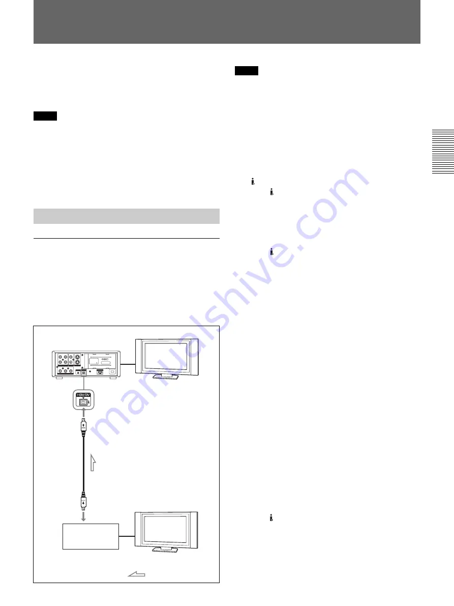
Rear view of the recorder
(this unit)
Monitor
i.LINK cable (not supplied)
i.LINK jack
Digital video equipment
with an i.LINK jack
Monitor
: Signal flow
Using the Unit as a Videocassette Recorder
This section describes the connections, settings and
operations necessary to perform recording on this unit.
The same settings and operations apply whether you
are using the unit for dubbing.
Notes
• For connection of the editing controller and its
peripheral devices, refer to the instruction manual of
the editing controller and that of the editing software
you use.
• Edit functions are specified by the editing software.
For details on the editing methods used, refer to the
instruction manual of the editing software.
Connections for Recording
To digital video equipment with an i.LINK
jack
The video and audio signals are sent with hardly any
degradation, enabling high-quality recording. The
signal flow is automatically detected so you do not
need to make separate connections for input and
output.
Notes
• When you record video from an HDV-compatible
equipment, set [VCR HDV/DV] on the [IN/OUT
REC] menu to [AUTO]. To record video from a
DVCAM/DV equipment, set [VCR HDV/DV] on the
[IN/OUT REC] menu to [AUTO] or [DV] before
connecting the i.LINK cable (p. 48).
If you change the setting after connecting the i.LINK
cable, the video equipment may not be able to
recognize the video signals correctly.
• This unit cannot input a copy-controlled program via
the HDV/DV jack.
• With the HDV/DV connection, the sound is
recorded in the same audio recording mode as that of
the source tape. To record in a different audio
recording mode from the source tape, connect as
shown in “To video equipment without an i.LINK
jack” on page 32.
• With the HDV/DV connection, data codes
(recording date/time, camera data) recorded on the
source tape are transmitted to the recorder (this unit).
As a result, when you play back a recorded tape on
this unit and press the DATA CODE button on the
Remote Commander, the same data codes as those
recorded on the source tape are displayed on the
monitor screen.
• If you record an image that is in playback pause
status, the image may be grainy.
• The unit cannot record video or audio separately.
• If you restart recording after a pause or stop, the
images recorded before and after restarting operation
will not be continuous.
• If you connect the output connectors of this unit to
the input connectors of a player or that of a monitor, a
humming noise may be generated or the image may
be distorted. If these phenomena occur, use the
INPUT SELECT switch to select a signal that is not
being input or disconnect the cables.
• This unit cannot record MPEG2 signals except HDV
1080i signals.
• There are some restrictions when you use EE pictures
output from the COMPONENT OUT jack of the unit.
Refer to
4
COMPONENT OUT (OUTPUT) jack in
“Location and Function of Parts” on page 15.
• If you record HDV format signals directly, to input
from the HDV/DV jack, the connection between the
signals will pause for a few seconds.
Summary of Contents for HVR-M10C
Page 2: ... 2 HVR M10C M10E M10J M10N M10P M10U SPECIFICATIONS ENGLISH JAPANESE ENGLISH JAPANESE ...
Page 3: ... 3 HVR M10C M10E M10J M10N M10P M10U ENGLISH JAPANESE ENGLISH JAPANESE ...
Page 5: ... 5 HVR M10C M10E M10J M10N M10P M10U ENGLISH JAPANESE ENGLISH JAPANESE ...
Page 13: ...1 5 HVR M10C M10E M10J M10N M10P M10U ENGLISH JAPANESE ENGLISH JAPANESE 1 SERVICE NOTE ...
Page 14: ...1 6 HVR M10C M10E M10J M10N M10P M10U ENGLISH JAPANESE ENGLISH JAPANESE ...
Page 15: ...1 7 HVR M10C M10E M10J M10N M10P M10U ENGLISH JAPANESE ENGLISH JAPANESE ...
Page 16: ...1 8E HVR M10C M10E M10J M10N M10P M10U ENGLISH JAPANESE ENGLISH JAPANESE ...
Page 123: ...5 13 5 REPAIR PARTS LIST 5 REPAIR PARTS LIST HVR M10C M10E M10J M10N M10P M10U J MODEL ...
Page 328: ...ENGLISH JAPANESE ENGLISH JAPANESE ...


