4-1
DSR-570WS/570WSP V1
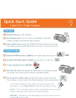
Basic Operations of Buttons
Button
Function
ADVANCE button
Changes the set value
Menu No.
+
(Increase)
SHIFT button
Moves between displayed digits
Menu No.
_
(Decrease)
RESET (MENU SET) button
Registers the set value
(Returns to the menu selection
mode)
Starts the adjustment
MENU button
Returns to the state before the
menu mode
Interrupts the adjustment
4-1. Menu (LCD)
The display window (LCD) of this unit enables setting of
the system functions of this unit, and VTR menus required
for adjustments and maintenance.
The VTR menus are divided into the following three:
.
USER MENU
For user operations.
.
SYSTEM MENU
Used to set various system functions of this unit (This
menu is not described in the instruction manual and
therefore cannot be used by users.)
.
MAINTENANCE MENU
Used for performing maintenance including adjustments.
4-1-1. User Menu
Operating the USER MENU
1.
Press the MENU button in the TC panel.
(The time data on the display window changes to the
menu display.)
The display window (LCD) displays “101 xxxx” and
the USER MENU is set. (Fig. A.)
2.
Press the ADVANCE button repeatedly until the Menu
No. on the display window (LCD) becomes the desired
Menu No.
Pressing the ADVANCE button (
+
button) will switch
and display the menu in the following order.
101
→
201
→
204 (DSR-570WS)/206 (DSR-570WSP)
···221(DSR-570WS)/214 (DSR-570WSP)
→
101···.
3.
To display the desired Menu No., press the SHIFT
button. The current value setting will blink, the value
will be enabled to be changed. (Fig. B.)
4.
To advance to the next digit, press the SHIFT button.
To change the set value, press the ADVANCE button
and display the desired value.
5.
Press the RESET (MENU SET) button.
The set value is registered, and the Menu No. blinks
again. (Fig. C.)
6.
Press the MENU button.
The display window (LCD) returns to the state before
the menu display.
n
If the MENU button is pressed during operations, the menu
will be exited without registering changes made in the
settings.
∞
H
MIN
SEC
FRM
1
dB
2
PB DATE NDF EXT-LK
HOLD
CLIP
TAPE
BATT
DIAG
E
F
RF SERVO HUMID SLACK
Li
-
-40
-30
-12
0
IP
CL CONT
OVER
OVER
WARNING
RESET
(MENU SET)
LIGHT
DISPLAY
ON
OFF
COUNTER
TC
U-BIT
-20
DVCAM
F
8
32k
F
8
48k
REC TIME SKIN DTL
EXT VTR
OUTPUT
VTR
TRIGGER
AUDIO LEVEL
AUDIO SELECT
AUDIO IN
CH-1
LITHIUM BATT
MENU
TTL
DUR
ON
OFF
OFF
TTL RESET
HYPER
GAIN
PARALLEL
PRESET
DATE/TIME
F-RUN
REGAIN
R-RUN
VJ MIC
WRR
SET
INT ONLY
EXT ONLY
FRONT
REAR
MIX
EXT
VBS
COMPONENT.
MONITOR SELECT
Y/C
SET
ClipLink
CONTINUE
ADVANCE
SHIFT
CH-1
CH-2
ON
OFF
FRONT MIC
LOW CUT
ON
OFF
MONITOR OUT
CHARACTER
ON
OFF
AUTO
MAN
SET UP
FILE
STD
CH-2
Display window (LCD)
RESET
(MENU SET)
button
SHIFT button
MENU button
ADVANCE button
Display window (LCD)
Initial display
Blinks when the set value is changeable
C
Blinking menu No. (When changed)
B
A
Section 4
Menu Setting
Summary of Contents for DSR-570WS
Page 1: ...DIGITAL CAMCORDER DSR 570WS DSR 570WSP SERVICE MANUAL Volume 1 1st Edition ...
Page 14: ......
Page 18: ......
Page 60: ...2 42 DSR 570WS 570WSP V1 1 2 3 4 5 6 7 8 90 ...
Page 68: ......
Page 86: ......
Page 118: ......
Page 198: ......
Page 204: ......
Page 222: ......
Page 248: ......
Page 249: ......