6-55
DSR-570WS/570WSP V1
.
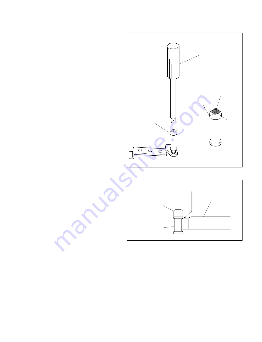
Use the service tool tape guide adjustment
screwdriver to adjust the height of the tape guides.
.
After adjusting the tape guide height, apply screw-
locking compound (Three bond 1401B) to the
screw of the upper flange of the tape guides.
[TG-1, TG-8 Guide]
1. Place the reference plate on the mechanical deck.
(Refer to Section 6-36. step 1.)
2. Place the guide gauge on the reference plate,
push it to the guide lightly, and check that there
is no clearance between the guide gauge and the
upper flange.
If this is not satisfied, rotate the flange and
adjust.
TG-2 upper flange
Guide shaft screw
TG-2 upper flange
Tape guide adjustment driver
Screw-
locking
compound
Guide gauge
TG-1 guide/
TG-8 guide
Upper flange
Specification : No clearance
Summary of Contents for DSR-570WS
Page 1: ...DIGITAL CAMCORDER DSR 570WS DSR 570WSP SERVICE MANUAL Volume 1 1st Edition ...
Page 14: ......
Page 18: ......
Page 60: ...2 42 DSR 570WS 570WSP V1 1 2 3 4 5 6 7 8 90 ...
Page 68: ......
Page 86: ......
Page 118: ......
Page 198: ......
Page 204: ......
Page 222: ......
Page 248: ......
Page 249: ......


