P32-EN – Subject to technical changes 04.11
29
Technician
Setting the controller and start-up
b) Circulation (optional):
•
Always leave control mode of circulation pump on
“Time” . . . . . . . . . . . . . . . . . . . . . . . . . . . . .
page 46
•
Circulation times,
(factory setting: Mo – Su: 00:10 – 00:00)
set required times, if necessary . . . . . . . . . . .
page 46
c) Heating circuit “HEAT CIR.1”
•
Set heating program of room heating
to “Time/Auto” . . . . . . . . . . . . . . . . . . . . . . .
page 34
•
If necessary, set the lowered temperature
(factory setting: 16°C) . . . . . . . . . . . . . . . . . .
page 37
•
Heating time and target room temperature heating circuit
(factory setting: Mo – Fr: 6:30 – 22:30, 20°C;
Sa/Su: 7:30 – 00:00, 20°C)
set times/target room temperature,
if necessary . . . . . . . . . . . . . . . . . . . . . . . . .
page 35
•
The slope is set to 0.8 at the factory. Depending on the
building/heating type, the correct heating curve must be
set to ensure that controller functions properly.
Set heating curve, if necessary . . . . . . . . . . .
page 37
•
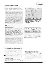
If no outdoor sensor is connected, “OPERATION: MAL-
FUNCTION” is displayed in the heating circuit. The con-
troller reads an outdoor temperature of 0°C and deter-
mines the corresponding flow target temperature from
the heating curve. However, it can be set to any flow
temperature by changing the mode of the controller
from “OUTDOOR TEMPERATURE” to “FIXED VAL” in
the heating curve menu (
page 39
) and by setting the
required flow temperature in normal mode for “T.Pre.-
20°C” and the required flow temperature in lowering
mode for “T.Pre.+10°C”. See “Setting the heating
curve in Temp mode”. . . . . . . . . . . . . . . . . . .
page 38
•
Only for underfloor heating with mixer circuit:
Reduce the maximum flow temperature of the mixed
heating circuit in the heating circuit of the controller
function menu to the required value.
If the maximum flow temperature is 35°C, for example,
in the heating circuit controller menu to which the
underfloor heating is connected, you must reduce
“T.PRE.MAX” from 70°C (factory setting) to 35°C,
“Setting flow temperature limit” . . . . . . . . . . . .
page 38
Of course, thermostatic flow temperature limiters
must be installed where they are prescribed.
•
Adjust the switch-off conditions of the heating pump to
the requirements of the system operator.
More information available on . . . . . . . . . . . .
page 40
d) Heating circuit “HEAT CIR.2” (optional):
If a second heating circuit is connected, carry out the
steps described under c).
e) Setting the flows of the solar circuits
For the control to function, there has to be a minimum
flow in the primary and secondary solar circuit set by the
minimum speed level.
Match the minimum speed level of both solar pumps to
the actual pressure loss at the solar circuits . . .
page 56
f) Swimming pool heating (optional):
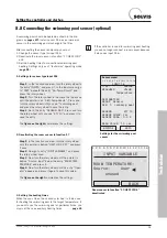
After connecting the swimming pool sensor, first set the
controller, . . . . . . . . . . . . . . . . . . . . . . . . . . . . .
page 31
then the heating times. Factory setting: Mo – Su: 0:00 –
0:00, which means deactivated, only solar heating is
possible; set required time, if necessary . . . . . .
page 45
g) Heat output in the solar circuit (optional):
Set impulse rate for heat quantity measurement at the
volume flow measuring unit, if necessary (accessories,
page 14
). . . . . . . . . . . . . . . . . . . . . . . . . . . . . .
page 30
h) Making a backup copy:
Always make a backup copy after completing any adjust-
ments to the SolvisControl . . . . . . . . . . . . . . . .
page 52
•
Please enter the start-up information in the start-up
report that is included.
•
Instruct the operator concerning the operation of the
SolvisControl.
•
Keep the entire installation and operating instructions
near the machine.
8.5.3 Documentation and instructions

