P32-EN – Subject to technical changes 04.11
28
Setting the controller and start-up
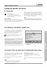
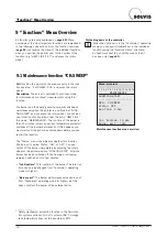
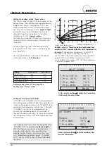
In the main menu, select the “Outputs” menu item.
Select the operating status of the relevant output
(e.g. “solar pump”). Set the “AUTO/...” operating
status by pressing and turning the rotary wheel.
Press again to save the operating mode. Use the
“BACK” button to return to the main menu.
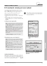
1 2 3 4 5 6 7 8 9 10
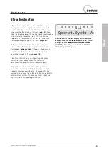
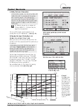
Operat.Syst: Ax
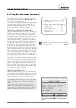
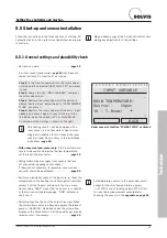
Section of SolvisControl display field. Overview of
outputs 1-10. For example, outputs 6 and 7 (solar
pumps) on this display are set to manual mode. If
collectors are connected, set them both to “AUTO”.
The hand symbol should then disappear.
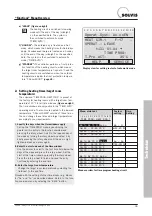
• Switch outputs to “AUTO”
>:
Check that all outputs are set to “AUTO” to ensure the
fault-free functioning of the controller. Simply look at the
top line in the display field (see
figure on right
). If you
see a hand symbol
below one of the numbers
(= numbers of outputs), the respective output is set to
manual mode and must be switched to automatic mode.
In the
figure on the right
output 6 and 7 (solar pumps)
are in manual mode and must be switched to “AUTO”
if collectors are connected.
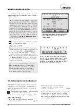
All parameters of the functional data set are preset for
proper function at the factory. References are made to
specific pages, where you can find more information on
changing values.
Please check whether the factory settings meet the
requirements of the system operator.
Check and, if necessary, change the following parameters:
a) Hot water heating:
•
Set hot water nominal temperature “T.WW.NOM
(factory setting is 48°C) . . . . . . . . . . . . . . . . .
page 13
8.5.2 Adjusting the functional data set
•
Auxiliary heating of the hot water buffer area
( (factory setting: Mo – Su: 00:10 – 00:00)
or set times as required . . . . . . . . . . . . . . . . .
page 43
•
Check that the hot water heating if functioning properly.
If the water is not hot enough: Check to see if the
thermal mixing valve (TMV) is set to 65°C at the hot
water station. (unscrew adjusting screw until stop and
screw in by a quarter turn).
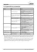
1 2 3 4 5 6 7 8 9 10 11 12 13 14
OUTPUTS
BROWSE
BACK
8: Mix Heat Cyc1
10: Mix Heat Cyc2
HAND
op:
OFF
9: cl:
OFF
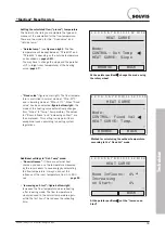
Open the mixer gradually by pressing the rotary
wheel at the pointer position
(switch to
“HAND” before)
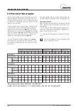
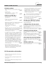
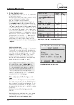
Open the “Outputs” submenu in the main menu. Now
turn the rotary wheel until “AUTO/OFF” or “AUTO/ON”
is selected for the “Mix Heat Cyc1” output (if a second
heating circuit is connected, do the same for “Mix Heat
Cyc2”). Set this entry to “HAND” by pressing, turning
and pressing the rotary wheel. Now move the pointer
to the entry “op: OFF” (
figure on right
) and press the
rotary wheel. The motor should now open the mixer as
long as the rotary wheel is pressed. If an incorrect run
occurs at plug “SM 1” or “SM 2”, swap the “op” and
“cl” connections (s.
section “Wiring diagram Solvis-
Control control board”, p. 66
).
•
If not performed during installation: For the mixers that
are connected, check the opening direction at the mixer
module as follows:
Switch the outputs from “HAND” back to “AUTO”
after checking the outputs.

