


P32-EN – Subject to technical changes 04.11
12
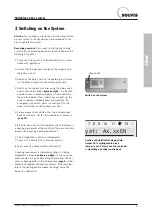
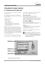
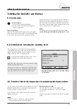
Operating the System Controller
You can adjust the factory settings to suit your individual
requirements.
If you want to adjust a value, use the rotary wheel to
position the pointer directly on the value and then
press the rotary wheel. Now turn the rotary wheel
until the required value appears and press it again
to save the adjusted value.
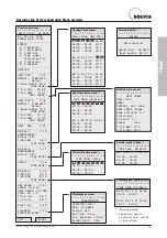
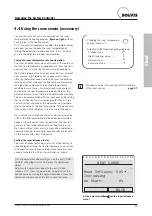
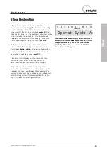
• “MESSAGE”
: Status or error messages are displayed
first if applicable. Explanation . . . . . . . . . . . .
Page 22f
• Time and date
: Before setting the time, first set the date
and specify whether it is “Summertime” or “Norm. time”.
Daylight savings changes occur automatically.
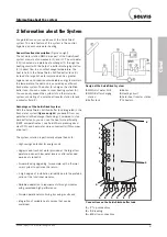
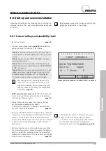
• “INPUTS”
: Displays temperature values for hot water
buffer (input 1), hot water (input 2), lower storage tank
(input 3), heating buffer (input 4), collector (input 8) and
external temperature (input 10). Sensor value “9999”
means that no sensor is connected or there is
sensor/cable breakage.
“-999” indicates a short circuit. In the example on the
right, the outdoor sensor is not connected. An external
temperature of 0°C is then accepted for the calculation
of the target flow temperature.
• “OUTPUTS”
: Press the rotary wheel for a list of con-
nected pumps or mixers in their respective switch state
(“AUTO/OFF” or “AUTO/ON”). The appendix “AUTO/...”
stands for automatic mode.
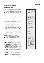
“HEAT CIR.1/2”: Settings for heat circuits
:
All functions are sensibly preset at the factory
(factory settings are provided in brackets).
• “OPERAT.”
: Set the operating mode to “Time/Auto”. If a
room sensor is connected, you will see “RAS”, set the
required operating mode on the room sensor. . . . .
page 15
• “Normal”
: Operating status of the controller. “Normal” =
normal operation; “Lower” = lowering mode.
• “T.Room.LOWER”
: Set the desired lowering temperature
(outside of the heating times, see below).
• “TIME PROG”
: Call this heating times menu to set the
target room temperature and heating times.
Set the time window and room temperature . .
page 35
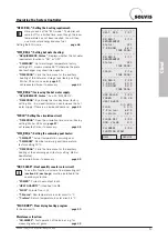
• “T.Pre.ACT”
: Actual value of the flow temperature in the
heating circuit. The display shows “9999” when no sensor
is connected.
• “T.Pre.NOM”
: Current flow target temperature in the
heating circuit.
• “HEAT CURVE”
: Set the slope (factory setting = 0.8) to
a value that is suitable for the building/heating system.
Setting the heat curve . . . . . . . . . . . . . . . . .
page 37
.
.
.
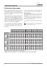
4.2 Basic settings
Function overview:
1
2 3 4 5 6 7 8 9 10 11 12 13 14
Operat.Syst: A2.08EN
MESSAGE
Excess Temp
since:
20.08. at 13:38
— — — — — — — — — — —
Sa. 20. 08. 2005
Summertime: 13 : 49
— — — — — — — — — — —
INPUTS
1: T.WW.Buffer
85°C
2: T.Warm Water
45°C
3: T.Ref.Sto
81°C
4: Temp. upper
heating buffer
87°C
8: T.Collector
95°C
10: T.Outdoor
9999°C
— — — — — — — — — — —
OUTPUTS
— — — — — — — — — —
HEAT CIR.1
F:17
OPERAT.: RAS
Normal
T.Room.LOWER: 16°C
TIME PROG:
T.Pre.ACT: 25.5°C
T.Pre.NOM: 5.0°C
HEAT CURVE:
— — — — — — — — — — —
HEAT CIR.2
F:18
OPERAT.: TIME/AUTO
T.Room.LOWER: 16°C
Normal
TIME PROG:
T.Pre.ACT: 26.1°C
T.Pre.NOM: 5.0°C
HEAT CURVE:
— — — — — — — — — —


