P32-EN – Subject to technical changes 04.11
22
SolvisControl System Controller Messages
The connected sensors are monitored. The following mes-
sages may arise:
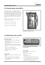
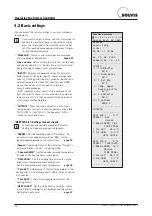
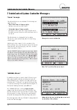
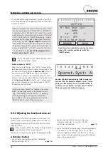
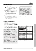
• “Short Circuit Sensor” (figure on right):
The line or sensor has a short circuit.
• “Interruption Sensor” (figure on right):
Interruption of the sensor line or sensor, which means
the cable or sensor is broken, and the electrical circuit is
not closed.
The affected sensor is displayed in the line below.
The sensor is reset automatically when it is functioning
correctly again.
Monitoring of sensor inputs 1 to 14 is included in the
factory settings. If you wish to exempt sensors that are not
connected from this monitoring (e.g. sensor 8 – collector
sensor), proceed as follows:
1 2 3 4 5 6 7 8 9 10 11 12 13 14
Operat.Syst: Ax.xxEN
HELP
SERVICE
Sensor
Short Circuit
Sensor
Interruption
2: T.Warm Water
1: T.WW.Buffer
Messages for a sensor malfunction
“Sensor” messages
An additional continuous function check of these sensors
takes place together with the monitoring of sensors S3
(tank reference sensor “T.Ref.Sto”) and S8 (collector tem-
perature sensor “T.Collector”) as required for the granting
of incentives according to the market incentive program of
the German federal government (www.BAFA.de):
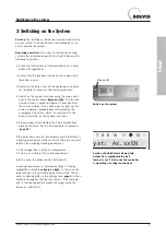
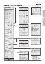
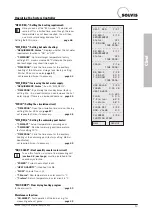
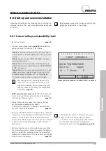
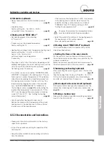
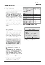
The “WARNING dT-Solar” message (
figure on right)
appears when the collector sensor is 60 K warmer than
the tank reference sensor for more than 30 minutes while
the solar pump is running. The sensor is reset automati-
cally when the temperature difference drops below 60 K.
This message means that very little heat is being collected
by the solar heat exchanger.
“WARNING dT-Solar”
1 2 3 4 5 6 7 8 9 10 11 12 13 14
BROWSE
BACK
SENSOR:
KTY
SENSOR CHECK: yes
SENSOR CORR.: 0.0 K
INPUT 8
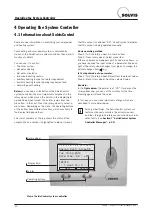
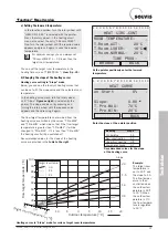
Enter “No” to switch off the sensor check.
1 2 3 4 5 6 7 8 9 10 11 12 13 14
HELP
SERVICE
WARNING
dT-Solar
since:
15.08. at: 12:09
Operat.Syst: Ax.xxEN
Malfunction in the solar circuit (despite excess heat,
no circulation at the collector)
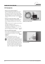
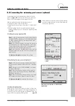
Use the “SERVICE” button to open the main menu. Select
the “Inputs” entry and press the rotary wheel. Select the
relevant input, e. g. “8: T.Collector”. Now move the pointer
to the entry next to “Sensor Check: Yes” (
figure on right
)
and set it to “No” by turning the rotary wheel until “No”
appears and then pressing it again. Press “BACK” twice to
return to the function overview.
7 SolvisControl System Controller Messages

