IQH1S 1U Enclosure
SECTION 1
IQH1SINS
23/11/06
www.snellwilcox.com
Version 1 Issue 4
1.6
INSTALLING/REMOVING A MODULE
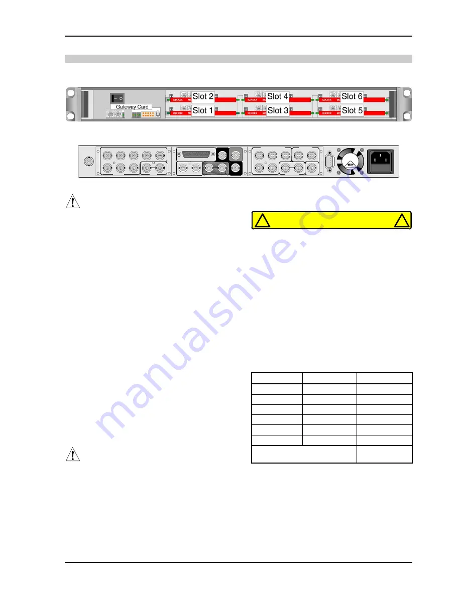
Internal View of 1U Mainframe.
Rear of 1U Mainframe fitted with two double width Modules and two single width Modules
Fuse
R
O
L
L
C
A
L
L
OUTPUT
INPUT
IQ
A
V
D
A
-2
4
1
2
3
5
7
6
8
100-240V~
60/50 Hz
1.8A
T
T2A H 250V
IQ
D
M
X
0
/1
_
1
6
-2
AES AUDIO OUT
1
2
SERIAL IN 1
SERIAL OUT
REFERENCE
GPI
SERIAL IN 2
COMPOSITE OUTPUT
REFERENCE
SERIAL IN
IQ
D
M
S
E
-2
SERIAL OUT
1
2
1
2
3
4
5
Warning
Before installing a new module into the enclosure
the
Configuration Rules
given below must be
followed.
The rear of the enclosure must have a full
complement of rear panels. Any vacant slots must
have a blank rear panel fitted
Configuration Rules
These rules limit the total power dissipation of
modules that can be installed in the box. Use the
module power ratings to calculate the total power
dissipated in the enclosure.
Module Power Rating
The power rating for each module is given in its
associated operation manual.
Available Power
The IQH1S Enclosure has 60 W of available
power. The power ratings of each module should
be added together and the total should not exceed
60 W.
The table opposite may be used for this calculation.
Warning
The sum of the module power ratings (calculated
using the method above) in the enclosure must not
exceed 60 W.
REFER TO USER MANUAL
BEFORE INSTALLING MODULES
!
!
Power Rating Table
Slot Position
Module Name
Power Rating
1
2
3
4
5
6
Total Power (Watts)
(60 W Maximum)