


5
The device address is set via DIP Switch SW4, which is a bank of eight switches. From left to
right (see Figure 3 below), these switches are designated as SW4-1 through SW4-8. The function
of these switches is as follows:
•
SW4-1
. This switch sets the baud rate for the internal communications line running between
the card and the FACP CPU. Set this switch to ON for 9600 baud communication.
•
SW4-2 through SW4-8
. These switches set the card’s address within the FACP. Refer to
Table 2 for a complete list of the switch settings for all of the possible card addresses.
FigureTag FD9-349-02
1
8
7
6
5
4
3
2
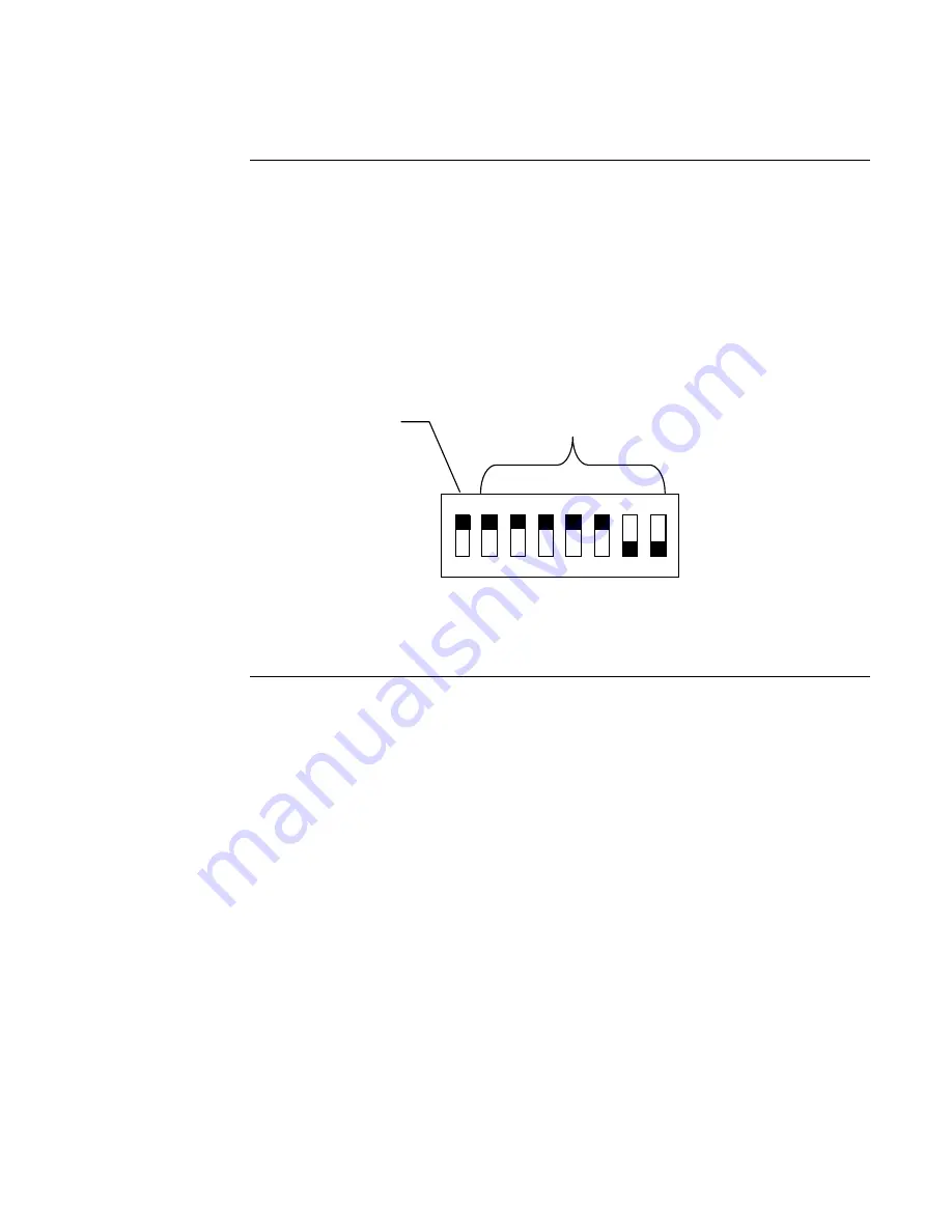
Figure 3. SW4 Switch Settings
Continued on next page
Configuring the SafeLINC FPII Card,
Continued
Setting the Baud
Rate and Address
ON
OFF
DIP Switches SW4-2 through
SW4-8 set the Card Address.
Figure 3 shows an Address of 3.
Baud Rate. Switch
(SW4-1) Must Be Set to
ON (9600 Baud)
Summary of Contents for SafeLINC 4020-0160
Page 2: ......
Page 55: ...49 MIS IT Configuration Worksheet...
Page 56: ...50 MIS IT Configuration Worksheet Continued...
Page 57: ......