


EM358x
44
Rev. 0.4
Parameter
Test conditions
Min
Typ
Max
Unit
Crystal ESR
100
kΩ
Start-up time
2
s
Current consumption
At 25°C, VDD_PADS=3.0 V
0.5
μA
5.3.5
Clock Switching
The EM358x has two switching mechanisms for the main system clock, providing four clock modes. Table 5-10
shows these clock modes and how they affect the internal clocks.
The register bit OSC24M_CTRL_OSC24M_SEL in the OSC24M_CTRL register switches between the high-
frequency RC oscillator (OSCHF) and the high-frequency crystal oscillator (OSC24M) as the main system clock
(SYSCLK). The peripheral clock (PCLK) is always half the frequency of SYSCLK.
The register bit CPU_CLKSEL_FIELD in the CPU_CLKSEL register switches between PCLK and SYSCLK to
produce the ARM
®
Cortex
TM
-M3 CPU clock (FCLK). The default and preferred mode of operation is to run the
CPU at the higher PCLK frequency, 24 MHz, to give higher processing performance for all applications and
improved duty cycling for applications using sleep modes.
The register bit USBSUSP_CLKSEL_FIELD in the CPU_CLKSEL register is used to divide the whole clock tree
by 4 when the EM358x (variants that support USB) is operating as a bus-powered USB device and USB
suspends the EM358x. Refer to Chapter 9, USB, for USB details.
In addition to these modes, further automatic control is invoked by hardware when flash programming is enabled.
To ensure accuracy of the flash controller’s timers, the FCLK frequency is forced to 12 MHz during flash
programming and erase operations.
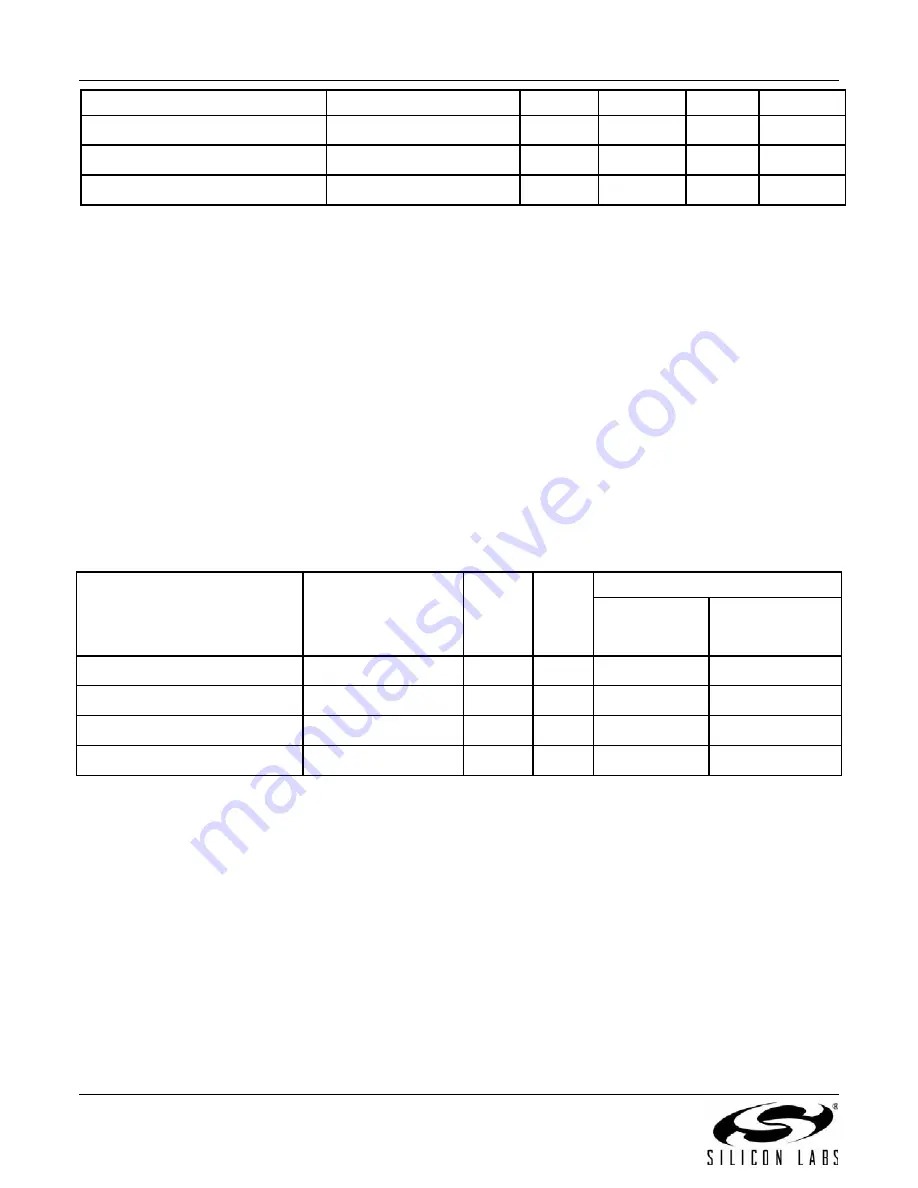
Table 5-10. System Clock Modes
OSC24M_CTRL_OSC24M_SEL CPU_CLKSEL_FIELD SYSCLK PCLK
FCLK
Flash
Program/Erase
Inactive
Flash
Program/Erase
Active
0 (OSCHF)
0 (Normal CPU)
12 MHz 6 MHz
6 MHz
12 MHz
0 (OSCHF)
1 (Fast CPU)
12 MHz 6 MHz
12 MHz
12 MHz
1 (OSC24M)
0 (Normal CPU)
24 MHz 12 MHz
12 MHz
12 MHz
1 (OSC24M)
1 (Fast CPU)
24 MHz 12 MHz
24 MHz
12 MHz
5.4 System Timers
5.4.1
Watchdog Timer
The EM358x integrates a watchdog timer which can be enabled to provide protection against software crashes
and ARM
®
Cortex
TM
-M3 CPU lockup. By default, it is disabled at power up of the always-on power domain. The
watchdog timer uses the calibrated 1 kHz clock (CLK1K) as its reference and provides a nominal 2.048 s timeout.
A low water mark interrupt occurs at 1.792 s and triggers an NMI to the ARM
®
Cortex
TM
-M3 NVIC as an early
warning. When the watchdog is enabled, the timer must be periodically reset before it expires. The watchdog
timer is paused when the debugger halts the ARM
®
Cortex
TM
-M3. Additionally, the Ember software that
implements deep sleep functionality disables the watchdog when entering deep sleep and restores the watchdog,
if it was enabled, when exiting deep sleep.
Ember software provides an API for enabling, resetting, and disabling the watchdog timer.
Summary of Contents for EMBER EM358 series
Page 2: ...EM358x 2 Rev 0 4 ...
Page 7: ...EM358x Rev 0 4 7 ...