


EM358x
178
Rev. 0.4
To detect missed captures reliably, read captured data in TIMxCCRy before checking the missed
capture/compare flag. This sequence avoids missing a capture that could happen after reading the flag and
before reading the data.
Note:
Software can generate IC interrupt requests by setting the corresponding TIM_CCyG bit in the TIMx_EGR
register.
10.3.6 PWM Input Mode
This mode is a particular case of input capture mode. The procedure is the same except:
Two ICy signals are mapped on the same TIy input.
These two ICy signals are active on edges with opposite polarity.
One of the two TIyFP signals is selected as trigger input and the slave mode controller is configured in reset
mode.
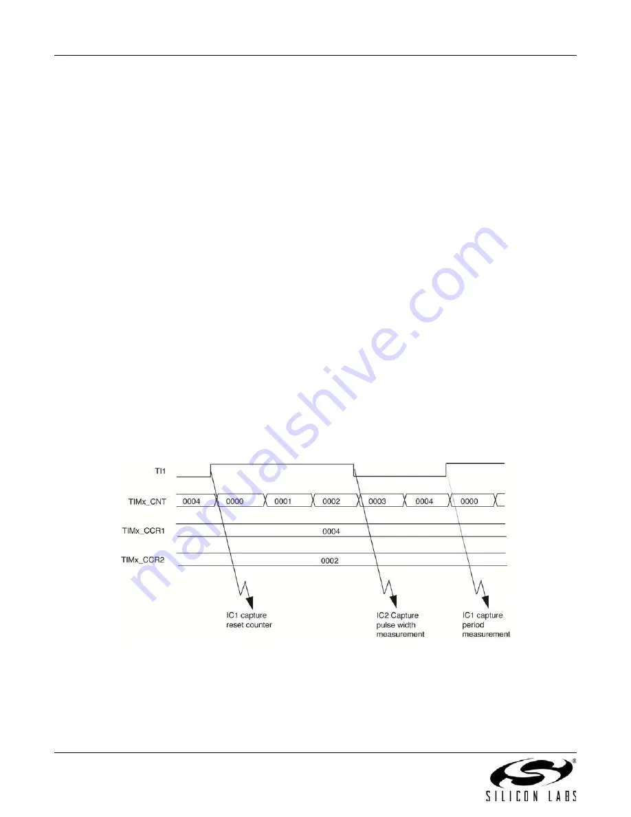
For example, to measure the period in the TIMx_CCR1 register and the duty cycle in the TIMx_CCR2 register of
the PWM applied on TI1, use the following procedure depending on CK_INT frequency and prescaler value:
Select the active input for TIMx_CCR1: write the TIM_CC1S bits to 01 in the TIMx_CCMR1 register (TI1
selected).
Select the active polarity for TI1FP1, used both for capture in the TIMx_CCR1 and counter clear, by writing the
TIM_CC1P bit to 0 (active on rising edge).
Select the active input for TIMx_CCR2by writing the TIM_CC2S bits to 10 in the TIMx_CCMR1 register (TI1
selected).
Select the active polarity for TI1FP2 (used for capture in the TIMx_CCR2) by writing the TIM_CC2P bit to 1
(active on falling edge).
Select the valid trigger input by writing the TIM_TS bits to 101 in the TIMx_SMCR register (TI1FP1 selected).
Configure the slave mode controller in reset mode by writing the TIM_SMS bits to 100 in the TIMx_SMCR
register.
Enable the captures by writing the TIM_CC1E and TIM_CC2E bits to 1 in the TIMx_CCER register.
Figure 10-20 illustrates this example.
Figure 10-20. PWM Input Mode Timing
10.3.7 Forced Output Mode
In output mode (CCyS bits = 00 in the TIMx_CCMR1 register), software can force each output compare signal
(OCyREF and then OCy) to an active or inactive level independently of any comparison between the output
compare register and the counter.
Summary of Contents for EMBER EM358 series
Page 2: ...EM358x 2 Rev 0 4 ...
Page 7: ...EM358x Rev 0 4 7 ...