MapIT G2 Hardware Installation Training Manual
Confidential – June 2014
8
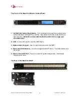
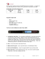
The Front of the MapIT G2 Master Control Panel
1. 24 RJ45 I/O Control Bus Outlets
– For connections to lower level components
(either directly to SPPs/SFPs or DCPs). Use either the RJ45s or the S310s (on
rear of panel).
DO NOT connect both the RJ45 and S310 of a single port
simultaneously.
2. LCD
- 4 Line LCD used to view the MCP Menu
3. Alphanumeric Keypad
- Use to input information into the MCP
4. Scroll and Enter Buttons
-
Used to navigate the MCP menu. The Enter button is in
the center.
5. Sensor Pen RJ45 Port
-
The pen is used for system diagnostics, circuit trace,
mapping and more.
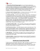
The Rear of the MapIT G2 MCP


