background image


MapIT G2 Hardware Installation Training Manual 


               Confidential – June 2014


63 


Certification Information 
 

Section 1: USA 


1.


SAFETY

 - UL 60950-1-1

ST

 Ed (2003) – Information Technology Equipment – Safety 

Part1: General Requirements 


2.


EMC


– 

FCC Part 15 (47CFR15) Class A 


This device complies with part 15 of the FCC Rules.  Operation is subject to the 
following two conditions: (1) This device may not cause harmful interference, and (2) 
this device must accept any interference received, including interference that may 
cause undesired operation.


Changes or modifications not expressly approved by Siemon could void the user’s FCC granted 
authority to operate the equipment. 
 

Note: this equipment has been tested and found to comply with the limits for a Class A 
digital device pursuant to part 15 of the FCC Rules.  These limits are designed to provide 
reasonable protection against harmful interference when the equipment is operated in a 
commercial environment.  This equipment generates 
uses 
and can radiate radio frequency energy and 
if not installed and used in accordance with the instruction manual 
may cause harmful interference to radio communications.  Operation of this equipment in a 
residential area is likely to cause harmful interference in which case the user will be 
required to correct the interference at their own expense. 


Section 2: Canada 


1.


SAFETY - CAN/CSA C22.2 No 60950-1-03 – Information Technology Equipment – 
Safety Part1: General Requirements 


2.

  EMC 

– 

ICES-003 Class A 

 
This Class A digital apparatus complies with Canadian ICES-003. 
Cet appareil numerique de la classe A est conforme a la norme NMB-003 du Canada. 


Summary of Contents for MapIT G2

Page 1: ...d by the Siemon Company Some of the product names mentioned herein have been used for identification purposes only and may be trademarks and or registered trademarks of their respective companies Information is subject to change without notice For the latest information visit our Web site at http www siemon com 2015 Siemon Company All Rights Reserved ...

Page 2: ... MapIT G2 System Design and Installation System Design Guidelines 21 System Configuration Examples 26 MapIT G2 Site Survey 29 Site and Requirement Survey Forms 32 Summary of Design Rules 34 MapIT G2 Hardware Installation 35 Installing MapIT G2 Control Bus Cables 37 Module 3 Navigating the MapIT G2 Menus Main Menu 40 Menu Navigation 41 Diagnostic Menu 42 Circuit Trace 50 Setup Menu 51 Mapping 56 Mo...

Page 3: ...n helps you better manage and protect your IT infrastructure The system tracks physical layer connections and IP enabled network devices in real time While other software solutions may detect IP devices on the network they cannot track them to their exact physical location The MapIT solution provides a detailed view of your infrastructure whether it is in your headquarters or at a remote office on...

Page 4: ...ion Automates the process of discovering documenting monitoring and managing the physical network s connections and its devices Asset Management Discovers and documents all IP enabled devices and ties them to a physical location Reports switch port utilization and availability Reports physical Layer port utilization and availability Rack space reports including available u space available contiguo...

Page 5: ...s SPP and Smart Fiber Enclosures SFE have the built in ability to track patch connections This connection information is transmitted to the Master Control Panel MCP supporting the patch zone The MCP relays this patch connection information via TCP IP over the customer s LAN WAN to the EagleEye database It is also possible to expand the capability of a given patching zone by installing Distribution...

Page 6: ...power to SPPs SFEs The DCP has its own power supply It is not powered from the MCP via the Control Bus Cable Patch Cord Connections Example When a MapIT G2 Patch Cable is inserted into a monitored port the probe located in the boot of the MapIT G2 Patch Cable touches the sensor pad on the SPP When the other end of the MapIT G2 Patch Cable is inserted into another monitored port a connection is cre...

Page 7: ...P immediately updates its database and then may trigger predefined events MapIT G2 System Components Master Control Panel MCP The MCP is the interface between the EagleEye software and all the Smart Panels Enclosures in the Patch Zone The MCP has two Ethernet ports on the rear of the unit for connecting to the TCP IP network It has 24 ports to connect either directly to Smart Patch Panels Fiber En...

Page 8: ...se either the RJ45s or the S310s on rear of panel DO NOT connect both the RJ45 and S310 of a single port simultaneously 2 LCD 4 Line LCD used to view the MCP Menu 3 Alphanumeric Keypad Use to input information into the MCP 4 Scroll and Enter Buttons Used to navigate the MCP menu The Enter button is in the center 5 Sensor Pen RJ45 Port The pen is used for system diagnostics circuit trace mapping an...

Page 9: ...onnections on both ports until a connection is established Connect the Ethernet port s to the TCP IP network via RJ45 Patch Cables T568A or B wired Cat 5e Shielded or higher 4 Two Ethernet Status LEDs There are LEDs on either side of the Ethernet RJ45s When the LED is not lit there is no connection When an LED is green it indicates the port has an active Ethernet connection 5 Two Power Connections...

Page 10: ...ntrol Bus For connections to SPP SFEs Use either these RJ45s or the S310s on rear of panel DO NOT connect both the RJ45 and S310 of a single port simultaneously If the RJ45s are used Siemon recommends putting the supplied S310 stuffer caps on the S310 ports on the rear of the panel If S310s are used use the Siemon RJ45 port blockers p n LL 05 sold separately Always use T568A wiring scheme for all ...

Page 11: ...te the cable coming from the MCP to either of these ports Use cat 5e solid shielded cable Terminate using T568A wiring scheme 4 Two Power Connections The DCP features two ports for redundant power The DCP is sold with one power supply If redundant power is required purchase a second power supply M PS Use of a non Siemon power supply will void the product warranty and may damage the unit Connect th...

Page 12: ...er than competing systems Finally it does not require proprietary cables to devices in the system The use of standard 5e solid shielded cable reduces cost and speeds installation time Also fewer cables are used to connect items in the system so less space is required for pathways The Smart Panels Enclosures also feature two LEDs and an LCD which provide a local user interface which can save signif...

Page 13: ...t for best viewing in a variety of lighting conditions 3 LEDs One green and one red LED for guidance on work orders instructions 4 Probe Pads Gold pad above each port This is the landing area for the pogo pin built into MapIT G2 Patch Cables This pad can also be used for circuit traces and diagnostics via the Pen Probe 5 Port Labeling Space Space provided for labeling of ports 6 Mounting mounts on...

Page 14: ...e information about the status of their network from the hardware layer and up anytime anywhere The Rear of the MapIT G2 SPP Flat Panel Angled Panel TERA Panel Rear View of the MapIT G2 Smart Patch Panel 1 Flat Panels have two S110 Control Bus Cable Connections Terminate the control bus cables routed from the MCP or DCP to the IN port Daisy chain Control Bus Cables from the OUT port of one panel t...

Page 15: ...e per connector Not required for angled panels 4 Rear Manager A rear manager is integrated into the panel Secure cables with Velcro or cable ties securely to the manager 4 Panel Grounding A ground lug is provided on the rear of the SPP for grounding to the rack or telecommunications ground TGBB The Smart Panel must be properly grounded for the system to function properly Smart Fiber Enclosures SFE...

Page 16: ...e SMPT enclosure Front view of the MapIT G2 Smart Fiber Enclosures SFE SMTP Rear of SFE 1 2 RJ45 Control Bus Cable Connections Connect the Control Bus cable routed from the MCP or DCP to the IN port on the inside of the SFE Daisy chain control bus cables from the OUT port of the SFE to the IN port of the SFE adjacent or below Up to 5 SFEs can be daisy chained together A redundant daisy chain path ...

Page 17: ...ween different MCPs or DCPs 2 Enclosure Grounding A ground lug is provided on the rear of the SFE to ground it to the rack or telecommunications ground The SFE must be properly grounded for the system to function properly 3 SFE vs SMTP The SFE is use for direct termination LC fusion splicing and LC trunks The SMTP is prepopulated with LC to MTP cassettes Use the SMTP when using MTP fiber trunks Ex...

Page 18: ...s than 2880 monitored ports 120 panels x 24 ports each ports can be served by a single MCP To create larger Patch Zones we add one or more DCPs to the system Therefore to design a system patch zones must be clearly planned and installed with an MCP and lower level components Note Detection of SPP SFP port connectivity is only possible between panels connected to the same MapIT G2 MCP How to Config...

Page 19: ...Bus Cable to the OUT port of the last panel in Group 2 In the event that the chain is broken at any point the panels in the daisy chain will still track connections and communicate with the MCP The system can also provide an alert in the event that the redundant daisy chain is broken The fault should be repaired at the earliest possible convenience to ensure greatest system reliability Control Bus...

Page 20: ...atch Zones Greater than 120 Panels Enclosures Use a combination of one MCP and up to 24 DCPs to create a Patch Zone with up to 65 000 ports The topology for this type of Patch Zone is shown below Only DCP 1 and connections for three of its ports are shown for clarity Large Patch Zone Topology Rules ...

Page 21: ...r system reliability In the above example the last panel in Group 1 is connected to the last panel in Group 2 In the event that the chain is broken at any point the system will still work and it will provide an alert of the fault The fault should be fixed at the earliest possible convenience 6 If you are using a redundant daisy chain both groups of panels must be connected to the same MCP or DCP Y...

Page 22: ...xample 1 In this small Patch Zone we have 50 panels connected to the MCP Each group of 5 panels is connected to a single port on the MCP In this case the 50 panels would occupy 10 of the 24 available ports in the MCP Note that a single MCP can connect to panels in adjacent racks as well as the same rack as the MCP ...

Page 23: ...used in one rack This configuration can be used if better visibility of LCD screens is desired The MCP is connected to each of the DCPs The SPPs SFEs on the same rack as the MCP can be connected directly to the MCP if desired Panels can be daisy chained as describe above however since there are very few panels in this example each of the 10 panels in each rack can be connected directly to individu...

Page 24: ...nnecting it to a DCP is no longer than 200 The MCP could support up to 18 more DCPs so there is plenty of room for expansion in this example MapIT G2 Patch Zone Sizing and Capacity Planning When creating a design from your site survey there are many decisions to be made based on customer specifications and needs The type and number of units used can vary depending upon the following criteria Real ...

Page 25: ...be based If additional information is needed the site administrator should be contacted to gather this information before proceeding At a minimum the following should be obtained Physical layout of the site Floor Plans Map etc Type of MapIT G2 equipment to be used Placement of MapIT G2 MCP and if required DCPs within each Patch Zone MapIT G2 Control Bus cables and maximum MapIT G2 Patch Cable leng...

Page 26: ...gin and where they terminate is essential in creating an effective end to end system With the client determine whether the existing documentation is satisfactory or whether the cables will need to be toned out for an existing installation NOTE A digital camera is useful to document existing conditions for future reference Rack Cabinet Configuration Rack Cabinet Configuration identifies the locatio...

Page 27: ...MapIT G2 Hardware Installation Training Manual Confidential June 2014 27 Example 1 ...

Page 28: ...cified on the drawings These components may be stacked above or below other components Since all MapIT G2components generate virtually no heat there is no need for additional spacing for cooling Use all of the installation hardware supplied with each unit Step 2 Make sure that all components are powered down before beginning terminations Disconnect all power supplies from the panels and the electr...

Page 29: ... the Patch Zone If firmware has not be loaded on the MCP the LCDs on the SPP SFEs will display UNLICENSED This is an indicator that the panels have power and are communicating with the MCP If firmware is loaded in the MCP then the starting assigned port number will be displayed on the SPP If the LCD on a panel is blank check the power connections to that panel 2 You can also look in the MCP or DCP...

Page 30: ...ingle ended Patch Cable cables are used they must be wired T568A and use Siemon Premium Category 5e 24 AWG shielded solid cable Rule for Termination of Control Bus Cable in a Small Patch Zone with a Single MCP If using the S310 and S110 blocks to terminate control bus cables Only use the S310 on the rear of the MCP Do not use the RJ45s on the front of the MCP Use optional RJ45 port blockers LL 05 ...

Page 31: ...erminate other end of the Control Bus cable to the IN S110 port on the first Patch panel in the daisy chain Use T568A wiring scheme Terminate drain wire to ground termination point Maximum cable length is 50 14m Terminate cable to OUT S110 block of the first panel in the daisy chain Terminate the other end of this cable to IN S110 block on the second Patch panel in the daisy chain The max length o...

Page 32: ...ion points The max length of each SPP Daisy Chain Cable is 3 1m Continue this daisy chain termination method for remaining panels max 5 panels per single daisy chain up to 10 for the redundant daisy chain If the redundant daisy chain is used connect the OUT S110 blocks of each of the last panels in the daisy chain Max length of this cable is 25 Redundant daisy chain can only be used for panels ser...

Page 33: ... caps to prevent access to the S310s All RJ45 outlets used in the system are grounded Patch Cables used in the Control Bus may be terminated in the field however you must always 1 use approved Siemon components 2 terminate cables using T568A wiring and 3 test Cables for continuity prior to installation in the system Plug Patch Cable into RJ45 ports on front of the MCP Plug the other end of the Cab...

Page 34: ... screen has timed out press any key to reactive the screen When power is applied to the MCP the unit will go through a power on self test In the unlikely even you see error codes listed on the screen contact Siemon Technical Support Otherwise the MCP will show the Main Menu screen See example below After the MCP is properly setup and working the Main Menu will show Mapping to indicate the system i...

Page 35: ...er keypad at the right of the LCD to enter numbers and letters To scroll to additional letters continue to press the key until the desired letter appears Entering Data Once you have scrolled to an item or have entered data press the Enter key to input your selection data Previous Page Next Use the prev and next buttons to move to the previous menu or forward to the next menu Multiple Users Multipl...

Page 36: ...Diagnostics mode scroll to Port Diagnostics and press Enter The following screen will appear Use the pen probe to touch a smart panel enclosure port pad for diagnostics Touch the probe pen to a sensor pad point and press the button on the pen The LED on the back of the probe pen will flash green after a few seconds and the port information will display If a Patch Cable is connected between panels ...

Page 37: ...ort icon and port number on the first line and a panel icon and panel ID on the second line The LCD screens will then alternate between showing this information for the connected panels An example is shown below If no Patch Cable is present only the LCD and LED on the probed panel will illuminate and display the port and panel information If a port is probed and the LCD LED does not illuminate and...

Page 38: ...ll down button to navigate to this option You can run diagnostics for all components in the system by selecting Check All and pressing Enter Please note that the system will suspend port tracking during the test If no errors are found the system will report All Components Passed Test If errors are found the system will list the problem components You can scroll to Reboot below the component and pr...

Page 39: ...us cable connections For the MCP and DCP check the power cable to make sure it is plugged in properly The LCD should have the Main Menu displayed If the unit still doesn t power up try a different power supply If these steps fail to repair the problem see the Troubleshooting section or contact Siemon Technical Support You can also run diagnostics on individual components Scroll to the desired opti...

Page 40: ... Enter You can try to clear errors on DCPs by selecting REBOOT and pressing Enter If rebooting does not resolve the issue see the troubleshooting section later in this document Check SPP To check an individual SPP scroll down to the Check SPP option below Check DCP option and press Enter The following screen will appear Use the probe pen to touch any port on the SPP you want to run diagnostics on ...

Page 41: ...atch cord connection diagnostics will run on both panels Scroll down below the first panel information to see the second panel info Connections This menu shows what is connected to the MCP or DCPs To go to the Connections menu select Connections from the Diagnostics menu and press Enter An example of what this screen looks like is pasted below The numbers 01 through 24 on the left of the screen ar...

Page 42: ... redundant daisy chain link connecting the last two panels you will see Link to chain on DCP or MCP port XX below the last panel If you are not seeing devices connected that should be connected check control bus cable connections Unlicensed Panels Previous versions of the MapIT software required a license for each patch panel EEC no longer requires this There is no panel specific license required ...

Page 43: ...can also go to the Unlicensed Panels menu to view details on unlicensed panels To access this information scroll down below the Unlicensed Panels line and any unlicensed panels will be listed here device type and serial number Reflash All Firmware for all items in the MapIT G2 system can be upgraded via the firmware upgrade process described in the EEC software manual Once new firmware is download...

Page 44: ...een will appear Use the probe pen to probe a port Touch a sensor pad or contact point on a Patch Cable Fiber Jumper Hold the button down on the probe pen and wait for the LED to flash green An example of the type of screen that will appear is shown below A graphical representation of the circuit is displayed on the top line The icons associated with the Class of the device are show in the circuit ...

Page 45: ...n a circuit you can use the left right scroll buttons to navigate and display the additional items Setup The Setup Menu allows you to set network product and language settings You can also clear unused panels that have been removed from the Patch Zone Scroll to Setup from the Main Menu this is off screen below the Work Order option and press Enter The following screen will appear Enter the passwor...

Page 46: ...f an invalid number is entered higher than 255 the MCP will default to 255 Check with you network administrator if you are having trouble with correct values for input Product Settings You can set the inactivity timeout period for all devices up to 999 minutes for MCP and DCP 30 seconds for SPP Scroll to the entry field and enter the desired timeout period for each type of device Once the data is ...

Page 47: ...section of this manual Language Selection This menu allows the user to select what language is displayed on the MCP DCPs and SPPs Input is always in English characters via the keypad The default language is English To select a language scroll to the desired language and press Enter An example of the Language screen is shown on the next page Product Information From the Setup Menu scroll to Product...

Page 48: ... screen will appear 1 Enter the new password press enter 2 Confirm the new password press enter If there is a mismatch between the New Password and the second entry of the New Password the following error code will appear Password Mismatch Please Try again Reenter the New Password on both lines and press enter The password must be a minimum of 4 characters with no spaces Clear Unused Panels ...

Page 49: ...e examples of when you would use this feature are Remove a panel from the Patch Zone Replace a defective panel board To clear unused panels scroll to the Clear Unused Panels option in the Setup Menu and press Enter The following screen will appear Make sure that the panels are disconnected from the MCP and or DCP Scroll down to CLEAR MEMORY and press Enter to clear unused panels Update Panel IDs T...

Page 50: ...Note Panel names will not be displayed until the MCP is connected to the EEC software and the panels have been mapped to the panels in the EEC database See mapping section below for details on how to map panels Mapping The mapping feature allows the user to associate physical panels enclosures with their virtual counterparts in the EEC software Prior to mapping panels you will have to create your ...

Page 51: ...f 24 is shown below To map items following the following steps 1 Select you MCP from the MCP pull down box If your MCP is not shown go to the MCP page and setup the MCP 2 Select a panel you want to map from the Navigation Tree to the left of the screen 3 Enter the port number of the patch panel The port number can be found on 2nd line of the patch panel LCD 4 Click on the Save button The panel and...

Page 52: ...he EM sends this information to the MCP while connected to the switch The technician then disconnects the EM and connects that end of the patch cord into an SPP The SPP port detects it has a connection since the 9th wire pogo pin is now grounded out to the switch This information is also sent to the MCP The MCP now has both ends of the patch cord connection and sends this information to the EEC da...

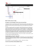
Page 53: ...em back 5 Set the IP address to 169 254 1 2 and the Subnet Mask to 255 255 0 0 6 Click OK and then Click OK in the next window 5 Open a windows command prompt start Run then type cmd and click Run 6 Ping the EM to make sure you have a good connection ping 169 254 1 1 If successful continue to next step if not troubleshoot IP settings 7 At the command prompt type tftp 169 254 1 1 put c path filenam...

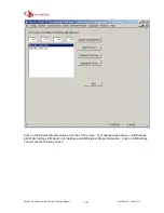
Page 54: ...fidential June 2014 54 Click on the Ethernet Module option at the top of the screen Four options will be shown EM Settings EM VLAN Settings EM Switch Info Settings and EM Data Exchange Information Click on EM Settings You will see the following screen ...

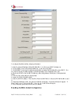
Page 55: ... address of the EM located on the underside of the unit 4 If not using DCHP enter the EM IP address subnet and gateway information in the appropriate boxes 5 Enter the community string for the switches 6 Leave the VLAN information blank 7 Enter the MCP IP address This should be the same MCP that is in the same TR that the EM is used in 8 Press Send Settings to EM If successful Send OK will appear ...

Page 56: ...ith IP address 169 254 1 1 and subnet 255 255 0 0 Configuring Switch Information in the EM From the G2 Management software go to Ethernet Module and select EM Switch Info Settings The following screen will appear To configure the switches that the EM will be used with complete the following steps 6 Enter the IP address of each switch There is no need to enter the MAC address 7 Once an IP address i...

Page 57: ...the switches If your network is not using VLANs you can skip this section of the EM setup To configure your EM to work with the VLANs on your network go to the EM VLAN Settings tab in the G2 Management software The following screen will appear Complete the following steps 1 Enter the VLAN starting and ending IP addresses 2 Enter the VLAN name or number 3 Press ADD 4 Repeat steps for al VLANs 5 Onc...

Page 58: ...ck 2 Make sure the MCPs are configured and mapping 3 Make sure all SPPs are mapped 4 If prior patch connections were made but not documented in the database enter patch connections via csv file import 5 Make sure 2161 update or higher is applied to the database Connecting Patch Cords Independent of Work Order Module 1 Press the black power button on the EM to power up the unit The LCD on EM will s...

Page 59: ...ons Siemon now offers an intelligent MapIT G2 TERA patch panel and patch cords Due to the unique port sharing capabilities of the TERA outlet there are some new features specific to these panels This section of the manual provides instructions specific to the installation and use of TERA MapIT G2 panels TERA MapIT Panel Installation Instructions TERA MapIT panels are installed the same way as MapI...

Page 60: ... Interconnect Mapping TERA panels in EEC 24 port Mapping When panels are used in the 24 port cross connect or 24 port interconnect mode you will use the normal panel mapping procedure Create TERA MapIT panels in EEC using model M SPPA T24K This will create a panel with 24 ports Mapping is done using the normal panel mapping procedure 48 port Mapping When you select the 48 port interconnect mode th...

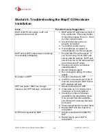
Page 61: ... server network settings MCP and server must be on the same subnet and in the same IP range 2 Check event log for connection status feedback 3 Restart analyzer agent 4 Run imanalyzer debug for further details No power on SPP 1 Check connections to SPP 2 If SPP is connected to DCP DCP must be connected to MCP before SPP displays will work SPP has power MCP has enough licenses but SPP still says unl...

Page 62: ...set Contact Siemon Technical Support Panel Names do not display 1 Make sure you are connected to the database Sync the MCP 2 Go to Setup Update Panel IDs Press enter This will force the MCP to collect the panel names from the software if available No information is displayed when I do a circuit trace 1 Make sure MCP is connected to the database server 2 Reboot or sync MCP if required I have enough...

Page 63: ...ply with the limits for a Class A digital device pursuant to part 15 of the FCC Rules These limits are designed to provide reasonable protection against harmful interference when the equipment is operated in a commercial environment This equipment generates uses and can radiate radio frequency energy and if not installed and used in accordance with the instruction manual may cause harmful interfer...

Page 64: ... CISPR 22 Class A Section 4 Australia NZ 1 SAFETY ACA TS 001 AS NZS 3260 2 EMC AS NZS 3548 Class A Section 5 EMC Immunity EN IEC61000 4 2 Electostatic Discharge Immunity EN IEC61000 4 3 Radiated Radio Frequency Immunity EN IEC61000 4 4 Electrical Fast Transient Burst Immunity EN IEC61000 4 5 Surge Immunity EN IEC61000 4 6 Immunity to Conducted Disturbances EN IEC61000 4 11 Voltage DIPS Short Inter...

Page 65: ...work MCP only Network Ethernet 10BASE T Number of Ethernet Ports 2 switching with LED status indicators Protocol TCP IP SNMP SNMPv1 LCD Display Size 256 x 64 pixels Type Graphic Backlight White LED Timeout User programmable 2 to 999 minutes Weight and Dimensi ons Height 44 45mm 1 75 inches Width 482 6mm 19 inches Depth 101 6mm 4 inches Weight 2 27kgm 5lbs Environ mental Operating Temperature 0o to...

Page 66: ...s Type Keystone Compatible Outlets Siemon keystone Z MAX UTP and F UTP outlets LCD Display Size 128 x 32 pixels Type Graphic Backlight White LED Timeout User programmable 3 to 30 seconds Bus Connectio ns Connection type S110 Ports 1 IN 1 OUT Protocol RS485 Bus Cable Type Category 5e solid shielded Environ mental Operating Temperature 0o to 45o C 32o to 113o F Operating Humidity Up to 90 non conden...

Page 67: ...de fiber connectors LCD Display Size 128 x 32 pixels Type Graphic Backlight White LED Timeout User programmable 3 to 30 seconds Bus Connectio ns Connection type RJ45 Ports 1 IN 1 OUT Protocol RS485 Bus Cable Type Category 5e solid shielded Environ mental Operating Temperature 0o to 45o C 32o to 113o F Operating Humidity Up to 90 non condensing Storage Temperature 40 o to 70o C 40o to 158o F Storag...

Reviews: