MapIT G2 Hardware Installation Training Manual
Confidential – June 2014
33
•
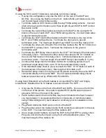
Terminate the open end of the cabl
e to the “IN” port of the first SPP in a daisy
chain. Use T568A wiring scheme. Terminate the drain wire on the ground
termination point
•
Terminate cable to “OUT” S110 block of the first SPP in the daisy chain.
Terminate the other end of this cable to “IN” S110 block on the second SPP in
the daisy chain. The max length of this cable is 3’ (1m)
•
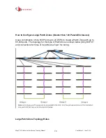
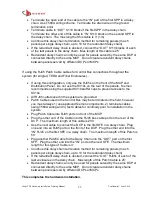
Continue this daisy chain termination method for remaining panels (max 5
panels per single daisy chain, up to 10 for the redundant daisy chain)
•
If the redundant daisy chain is desired, connec
t the “OUT” S110 blocks of each
of the last panels in the daisy chain. Max length of this cable is 25’
•
Redundant daisy chain can only be used for panels served by the same DCP or
connected directly to the same MCP. Do not create redundant daisy chains
between panels served by different DCPs or MCPs
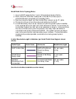
If using the RJ45 Patch Cable cables for Control Bus connections throughout the
system (for Angled, TERA and Fiber Enclosures
)…
•
If using this configuration, only use the RJ45s on the front of the MCP and
Distribution Panel. Do not use the S310s on the rear of the panels. Siemon
recommends using the supplied S310 stuffer caps to prevent access to the
S310s.
•
All RJ45 outlets used in the system are grounded.
•
Patch Cables used in the Control Bus may be terminated in the field, however
you must always 1) use approved Siemon components, 2) terminate cables
using T568A wiring and 3) test Cables for continuity prior to installation in the
system
•
Plug Patch Cable into RJ45 ports on front of the MCP
•
Plug the other end of the Cable into the RJ45 bus cable port on the rear of the
DCP. The maximum length of this cable is 200’
•
Use the next cable to connect the DCP to the first SFE in a daisy chain. Plug
one end into an RJ45 port on the front of the DCP. Plug the other end into the
“IN” RJ45 on the first SFE in a daisy chain. The maximum length of this Patch is
50’
•
Plug another Patch Cable for the Daisy Chain into the “OUT” port on the first
SFP. Plug the other end in
to the “IN” port on the next SFE. The maximum
len
gth for this type of Cable is 3’
•
Continue this daisy chain termination method for remaining panels (max 5
panels per single daisy chain, up to 10 for the redundant daisy chain)
•
If the redundant daisy chain is desired
, connect the “OUT” RJ45s of each of the
last enclosures in the daisy chain. Max length of this Patch Cable is 25’
•
Redundant daisy chain can only be used for panels served by the same DCP or
connected directly to the same MCP. Do not create redundant daisy chains
between panels served by different DCPs or MCPs
This completes the hardware installation.

