MapIT G2 Hardware Installation Training Manual
Confidential – June 2014
44
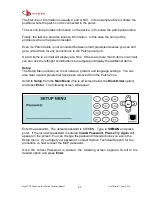
Scroll down to
UPDATE ALL
and press
Enter
. This will download firmware to SPPs
and DCP in the patch zone.
Circuit Trace
Note that Circuit Trace works differently for interconnect mode. The instructions here
pertain to cross-connect mode. Instructions for interconnect mode are provide in the
Interconnect Mode section later in this manual.
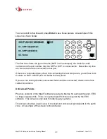
Circuit Trace lets you see an end-to-end circuit on the MCP or DCP screen. To enter
the Circuit Trace menu, scroll to
Circuit Trace
on the
Main Menu
and press
Enter
.
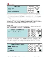
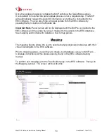
The following screen will appear:
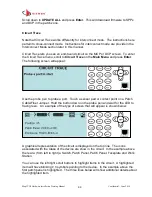
Use the probe pen to probe a port. Touch a sensor pad or contact point on a Patch
Cable/Fiber Jumper. Hold the button down on the probe pen and wait for the LED to
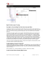
flash green. An example of the type of screen that will appear is shown below:
A graphical representation of the circuit is displayed on the top line. The icons
associated with the Class of the device are show in the circuit. In the example above
there are: (from left to right) a Switch, Patch Panel, Patch Panel, Faceplate and Work
Station.
You can use the left/right scroll buttons to highlight items in the circuit. A highlighted
item will have blinking
> <
symbols pointing to the device. In the example above the
first patch panel is highlighted. The three lines below will show additional details about
the highlighted item.

