MapIT G2 Hardware Installation Training Manual
Confidential – June 2014
29
redundant connection between the panels connected from port 1 and port 2 on an
MCP or DCP).
Step 4.
Connect a ground wire from the back of all components (MCP, DCPs, SPPs, SFEs) to
the telecommunications ground. Proper grounding is critical to proper functioning of
the MapIT G2 system
Step 5.
Install the provided power supply cords in each MCP and DCP (if used), then plug
each of them into the electrical power outlets.
Step 6.
Check the power connections: There are two methods of doing this:
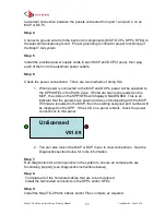
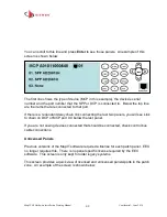
1. When power is connected to the MCP and DCPs, power will be supplied to
the SPPs/SFEs in the Patch Zone. If firmware has not be loaded on the
MCP, the LCDs on the SPP/SFEs will display UNLICENSED. This is an
indicator that the panels have power and are communicating with the MCP.
If firmware is loaded in the MCP, then the starting assigned port number will
be displayed on the SPP. If the LCD on a panel is blank, check the power
connections to that panel.
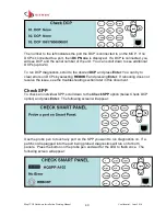
2. You can also look in the MCP or DCP menu to view connections. See the
Diagnostics section below for more information.
Step 7.
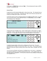
Run Diagnostics for all components in the system to ensure all components are
functioning properly (see Diagnostics instructions below).
Step 8.
Terminate all of the horizontal cables that are to be monitored.
Install the terminated connectors in the SPPs and/or SFEs
Step 9.
Install the MapIT G2 Patch Cables and/or Fiber Jumpers as required.
V01.09
Unlicensed

