MapIT G2 Hardware Installation Training Manual
Confidential – June 2014
28
Site and Requirement Survey Forms
Siemon will provide the following documents to collect data required to configure
the MCPs and build the database. These must be completed and returned to Siemon
in order to build the EEC database.
-
MCP Network Settings and Locations
-
Database Build
-
Discovery Questionnaire
-
Email Server and Events
-
Floor Graphics
-
Rack/Cabinet/Faceplate Locations
-
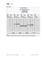
Rack Elevations
MapIT G2 Hardware Installation
The following steps for the hardware installation of the MapIT G2 Components can be
used as a basic checklist to insure that all of the steps have been accounted for during
installation.
Step 1.
Mount the MapIT G2 MCP, DCPs (if applicable) and SPPs/SFEs in the equipment
rack(s) as specified on the drawings. These components may be stacked above or
below other components. Since all MapIT G2components generate virtually no heat,
there is no need for additional spacing for cooling. Use all of the installation hardware
supplied with each unit.
Step 2.
Make sure that all components are powered down before beginning terminations.
Disconnect all power supplies from the panels and the electric power outlets.
Step 3.
Connect the Control Bus Cables from the MCP to the DCPs (if applicable) or
SPPs/SFEs using the proper cable and termination practices. Connect the daisy chain
Control Bus cables between the Patch panels. If desired, connect the last panel in
each daisy chain to another panel to create a redundant daisy chain. The redundant
cable connection must connect 2 daisy chains on the same MCP or DCP. Do not span
across MCPs and/or DCPs. Siemon recommends that the daisy chained ports be
connected between panels on adjacent ports on a MCP or DCP (for example, create a

