Appendix
A-9
7SJ63 Manual
C53000-G1140-C120-1
7SJ635
∗
–
∗
D/E
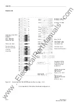
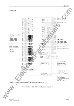
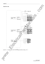
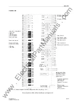
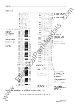
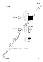
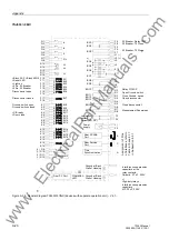
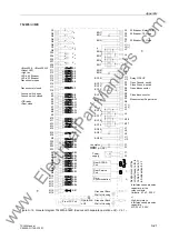
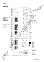
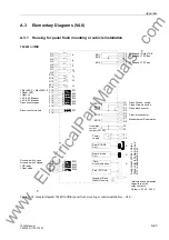
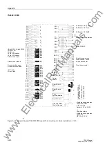
Figure A-4
General diagram 7SJ635
∗
–
∗
D/E (panel flush mounting or cubicle installation) – V4.1 –
Power
Rear SCADA
Port
Time
Rear Service
B
C
A
Ground at Back
supply
Wall of Housing
F1
F2
( )
~
+
-
Synchronization
Interference suppression
capacitors at the
Ceramic, 4.7 nF, 250 V
*
)
relay contacts,
Interference suppression
capacitors
MP, 22 nF, 250 V
High-duty relays
Q1
Q2
I
A
Q7
Q8
3I
0
Q3
Q4
I
B
Q5
Q6
I
C
R17
R18
V
c
R14
R16
V
a
R15
F17
F18
BI7
V
b
F10
F11
BI1
F13
F15
F16
F14
F12
BI2
BI4
BI5
BI6
BI3
K1
K2
BI8
K4
K6
K7
K8
K3
BI9
BI11
BI12
BI13
BI14
BI10
K9
K5
BI15
K10
K11
BI16
K13
K14
K12
BI17
BI19
BI18
K15
K16
R9
R10
R12
R13
R11
M1
M2
M4
M6
M7
M8
M3
M9
M5
M10
M11
M13
M14
M12
M15
M16
BI20
BI21
BI22
BI24
BI23
BI25
BI26
BI28
BI29
BI30
BI31
BI27
BI32
BI33
BI34
BI36
BI35
BI37
F9
F7
BO3
F6
F8
BO1
F5
BO2
J11
J12
J7
J9
J8
R1
R2
BO11
R3
BO12
R4
BO13
R5
R6
R7
R8
L11
L12
L7
L9
L8
J1 (–)
J2 (+)
BO4
J3
J4
K18
K17
BO5
BO6
BO7
Live status
F3
F4
contact
*
)
BO8
BO9
BO10
BO14
BO15
BO16
BO17
BO18
BO19
L1 (–)
L2 (+)
L3
L4
M18
M17
BO20
BO21
BO22
Jumper (NO, NC)
*
)
Port
Front PC Port
>Block 50-2, >Block 50N-2
>Reset LED
>Light on
>52-b, 52 Breaker
>52-a, 52 Breaker
Disconnector open
Disconnector closed
Ground. switch open
Ground. switch closed
>CB ready
>Door close
52 Breaker, Relay TRIP
52 Breaker, 79 Close
Open Ground. switch
Close Ground. switch
Open disconnector
Close disconnector
Measurement Supervision
52 Breaker, 79 Close
Relay PICKUP
As
si
gnm
en
t o
f Pin
s
o
f In
terfa
c
e
s
,
refe
r to
T
abl
e 8-1
a
nd
in
Su
bse
c
ti
on
8.2
www
. ElectricalPartManuals
. com


