Installation and Commissioning
8-25
7SJ63 Manual
C53000-G1140-C120-1
of 67-TOC is in the direction of the line (or object to be protected). This is not neces-
sarily identical with the direction of the normal network current flow or the load current
flow for this test. For all three phases, the corresponding power flow directional mes-
sages must be reported properly. If all directions are incorrect, then there is conflict
between the polarity of the current transformers and the polarity set under Address
&76WDUSRLQW
, in
36\VWHP'DWD
. The polarity of the current transformers
must be determined and properly set in the 7SJ63 according to Sub-section 6.1.1. If
the directional data are diverse, then individual phases in the current or voltage con-
nections are interchanged, or the phase sequence is not correct. The connections
must be checked and corrected.
Capacitive currents, which can be caused, for example, by under-excited generators,
can occasionally produce limit conditions with respect to the directional characteristic
of 67-TOC. The result can be undefined or diverse directional data in this test. In such
a case, use the indications of real power P, reactive power Q, and the power factor
cos
ϕ
in the metering of the device to determine the position of the complex (apparent)
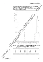
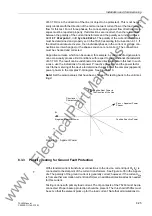
power phasor in the complex P-Q diagram. See Figure 8-13.
Note! Set the pickup values that have been changed for testing back to the valid set-
tings!
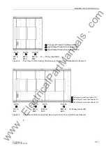
Figure 8-13
Apparent Power
8.3.3
Polarity Testing for Ground Fault Protection
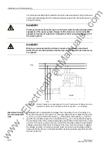
With standard current transformer connections to the device, current input 3I
0
(I
4
) is
connected to the starpoint of the current transformers. See Figure A-35 in the Appen-
dix. The polarity of the ground current is generally correct; however, if the current I
Ns
is from another summation current transformer, an additional directional test is needed
for this current.
Testing is done with primary load current. The trip contacts of the 7SJ63 must be dis-
connected. Proper backup protection should be present. The threshold of 50Ns must
be set so that the element picks up for the load current. Note that all simulations do
Positive Reactive Power
Negative Reactive Power
S
Load
= Apparent Power
P
Q
Directional
Characteristic
Phasor
Positive Real Power in
the Direction of the Line
www
. ElectricalPartManuals
. com

