Functions
6-41
7SJ63 Manual
C53000-G1140-C120-1
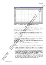
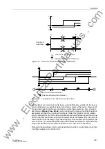
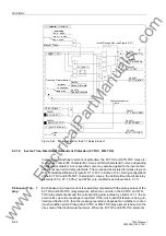
Figure 6-19
Overcurrent Protection for Parallel Transformers
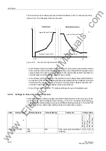
Figure 6-20
Transmission Lines with Sources at Each End
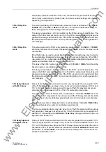
All directional overcurrent elements, inverse and definite time, enabled in the device
may be blocked via an external signal to the binary inputs of the device. Removal of
the external signal to the binary input will re-enable these elements. Also, a feature
described as Manual Close Mode can be configured to improve fault clearing times
associated with Switch-on-to-Fault Conditions. Under this situation, the time delay
may be defeated for one of the three directional overcurrent phase elements and one
of the three directional overcurrent ground elements via an impulse from the external
control switch, thus resulting in high speed tripping. This impuls is prolonged by a pe-
riod of 300 ms. The directional phase and ground elements utilized for high speed trip-
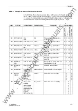
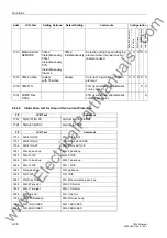
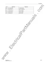
ping in this situation are selected at addresses
and
respectively.
Pickup and delay settings may be quickly adjusted to system requirements via dynam-
ic setting swapping (see Section 6.4).
t
t
Lastfluß-
richtung
A
B
I
II
Überstromzeitschutz
gerichteter Überstromzeitschutz
Direction of
Load Flow
Time-Overcurrent Protection
Directional Overcurrent Protection
Überstromzeitschutz
gerichteter Überstromzeitschutz
t
t
G
G
Time-Overcurrent Protection
Directional Overcurrent Protection
www
. ElectricalPartManuals
. com

