Installation and Commissioning
8-8
7SJ63 Manual
C53000-G1140-C120-1
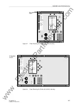
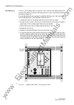
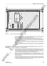
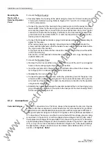
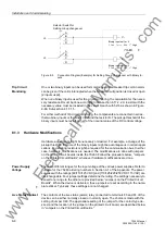
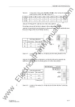
Figure 8-5
Connection Diagram (Example) for Setting Group Changeover with Binary In-
puts
Trip Circuit
Monitoring
One or two binary inputs can be used for monitoring a circuit breaker trip coil. An alarm
can be given if the coil is interrupted when the breaker circuit position is closed or open
(2 inputs used).
When
one
binary input is used for trip circuit monitoring, the calculation for the neces-
sary resistance R must be done according to Sub-section 6.17.2.2. A resistor with the
necessary value must be included in the circuit branch with 52/b as shown in Figure
6-60, Sub-section 6.17.1.5.
For either method of trip circuit monitoring, the components are connected in series -
the two binary inputs or the binary input and the resistor R. The pickup threshold of the
binary inputs must be less than half of the nominal value of the DC control voltage.
8.1.3
Hardware Modifications
Hardware adjustments might be necessary or desired. For example, a change of the
pickup threshold for some of the binary inputs might be advantageous in certain appli-
cations. Terminating resistors might be required for the communication bus. In either
case, hardware modifications are needed. The modifications are done with jumpers
on the printed circuit boards inside the 7SJ63. Follow the procedure below, “Jumpers
on the Printed Circuit Boards”, whenever hardware modifications are done.
Power Supply
Voltage
There are different ranges for the input voltage of the various power supplies. Refer to
the data for the 7SJ63 ordering numbers in Section A.1 of the Appendix. The power
supplies with the ratings [60/110/125 VDC] and [110/125/220/250 VDC 115 VAC] are
interchangeable. Four jumper settings determine the rating. The settings necessary to
convert one range to the other are provided below, “Jumpers on the Printed Circuit
Boards”. When the device is delivered, these jumpers are set according to the name-
plate sticker. Typically, these settings are not changed.
Live Status Contact
The contacts of the live status (alarm) relay connected to terminals F3 and F4 of the
device can be either normally closed or normally open. The choice is made with the
setting of jumper X40. The appropriate setting of the jumper for the contact type de-
sired, and the location of the jumper on the printed circuit board, are described below
in “Jumpers on the Printed Circuit Boards.“
A
B
C
D
V–
V+
Selector Switch for
Setting Group changeover
Binary input set for:
“
!6HW*URXS%LW
”, High
A
B
C
D
V–
V+
Binary input set for:
”
!6HW*URXS%LW
”, High
7SJ63
www
. ElectricalPartManuals
. com

