Appendix
A.4 Interconnecting signals in the inverter
Converter with control units CU250D-2
Operating Instructions, 04/2015, FW V4.7.3, A5E34261542B AB
369
Binectors and connectors
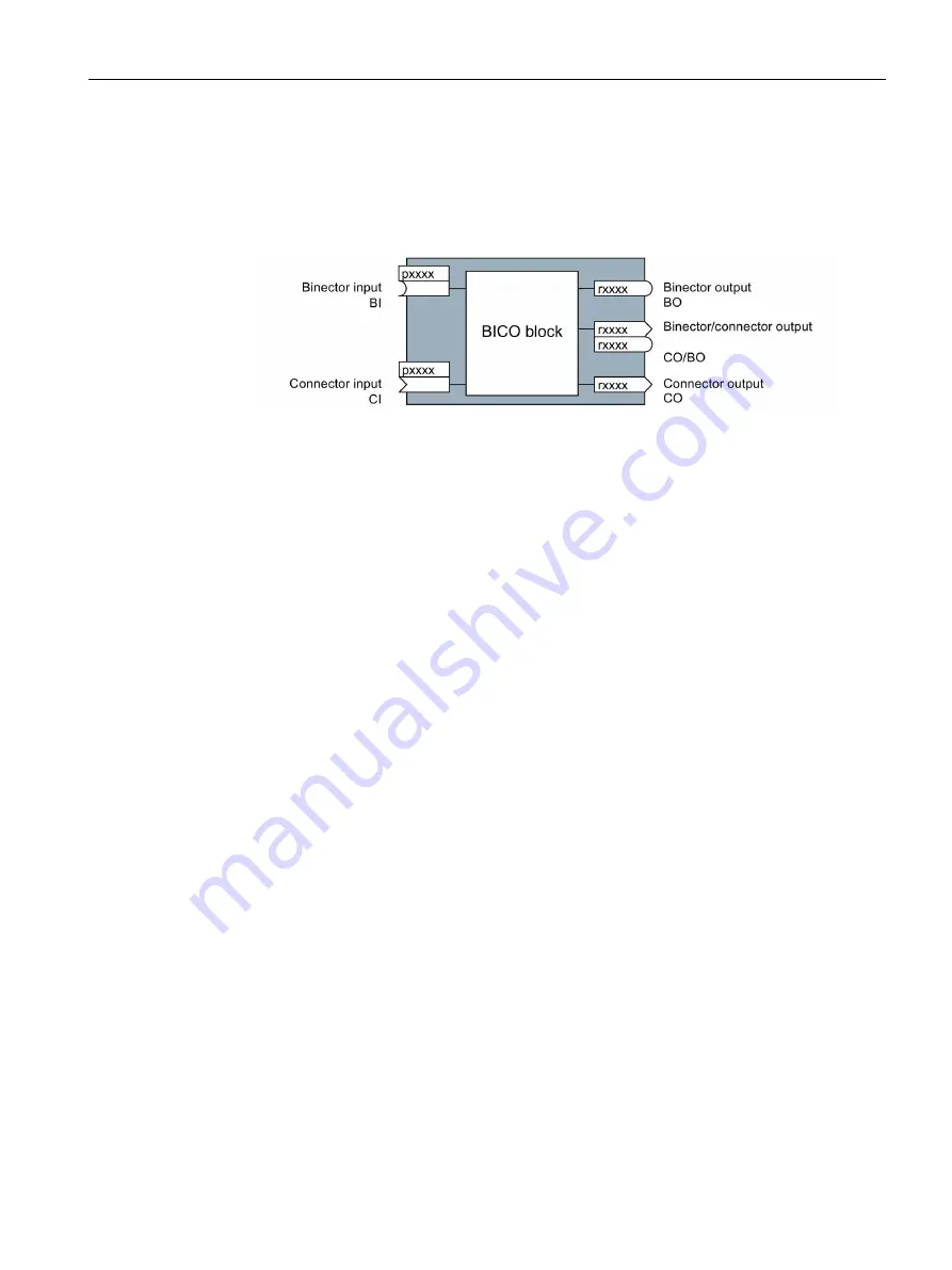
Connectors and binectors are used to exchange signals between the individual blocks:
●
Connectors are used to interconnect "analog" signals. (e.g. MOP output speed)
●
Binectors are used to interconnect "digital" signals. (e.g. 'Enable MOP up' command)
Figure A-4 Symbols for binector and connector inputs and outputs
Binector/connector outputs (CO/BO) are parameters that combine more than one binector
output in a single word (e.g. r0052 CO/BO: status word 1). Each bit in the word represents a
digital (binary) signal. This summary reduces the number of parameters and simplifies
parameter assignment.
Binector or connector outputs (CO, BO or CO/BO) can be used more than once.
When must you interconnect signals in the converter?
If you change the signal interconnection in the converter, you can adapt the converter to a
wide range of requirements. This does not necessarily have to involve highly complex
functions.
Example 1: Assign a different function to a digital input.
Example 2: Switch the speed setpoint from the fixed speed to the analog input.
How much care is required when you change the signal interconnection?
Always take care when establishing internal signal interconnections. Note which changes
you make as you go along since the process of analyzing them later can be quite difficult.
The STARTER commissioning tool offers signals in plain text and simplifies their
interconnection.
Where can you find additional information?
●
This manual is sufficient for simple signal interconnections (e.g. assigning a different
function to digital inputs).
●
The parameter list in the List Manual is sufficient for more complex signal
interconnections.
●
You can also refer to the function diagrams in the List Manual for complex signal
interconnections.


