S5-95F
Addressing
6.4
Analog Modules
You can plug analog modules only into slots 0 through 7. Whereas only the information "0" or "1"
("ON" or "OFF") per channel can be transferred from or to a digital module (memory requirement 1
bit), it is possible to transfer 65,536 different items of information per channel from or to an analog
module. The memory requirement is 16 bits=2 bytes=1 word.
The modules are addressed byte-by-byte or word-by-word with load or transfer operations.
The programmable controller takes this increased memory requirement into account when an analog
module is plugged in.
•
Eight bytes (=four words) are reserved per slot.
•
The slot addressing area is changed.
•
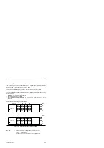
The permissible address space extends from byte 64 (slot 0, channel 0) to byte 127 (slot 7,
channel 3).
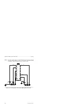
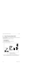
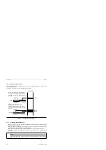
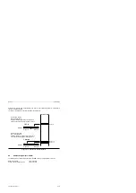
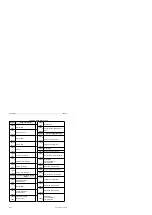
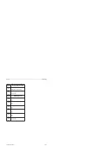
Figure 6-5. Address Assignment for Analog Modules
Channel
number
Slot number
S5-95F
basic unit
64+65
66+67
68+69
70+71
6
4
2
0
Slot number
a a a a a a a a a a a
a a a a a a a a a a a
a a a a a a a a a a a
a a a a a a a a a a a
80+81
82+83
84+85
86+87
96+97
98+99
100+101
102+103
112+113
114+115
116+117
118+119
Channel
number
0
1
2
3
7
5
3
1
Address assignments for analog modules in subunit B
Address assignments for analog modules in subunit A
S5-95F
basic unit
72+73
74+75
76+77
78+79
a a a a a a a a a a a
a a a a a a a a a a a
a a a a a a a a a a a
a a a a a a a a a a a
88+89
90+91
92+93
94+95
104+105
106+107
108+109
110+111
120+121
122+123
124+125
126+127
0
1
2
3
Examples:
1)
Analog module in slot 2, channel number 0 bytes 80 and 81
2)
Channel 1 address of an analog module in slot 5?
Solution:
bytes 106+107
Bytes 92 and 93 Analog modules in slot 3, channel number 2
EWA 4NEB 812 6210-02
6-5


