S5-95F
Contents
Page
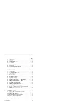
5.6
Connection of Non-Failsafe I/O Modules
. . . . . . . . . . . . . . . . . . . . . . . .
5 - 19
5.7
Power Supplies for the S5-95F . . . . . . . . . . . . . . . . . . . . . . . . . . . . . . .
5 - 23
5.8
Electrical Potentials for the Onboard and External I/Os
. . . . . . . . . . . . . .
5 - 24
5.8.1
Onboard I/Os of the S5-95F Programmable Controller
. . . . . . . . . . . . . .
5 - 24
5.8.2
Potential Bonding and Galvanic Isolation of External I/Os
. . . . . . . . . . . .
5 - 25
5.9
Grounded or Non-Grounded S5-95F Configuration
. . . . . . . . . . . . . . . . .
5 - 27
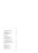
6
Addressing . . . . . . . . . . . . . . . . . . . . . . . . . . . . . . . . . . . . . . . . . . . . . . . . . .
6 - 1
6.1
Address Assignments for Onboard I/Os . . . . . . . . . . . . . . . . . . . . . . . . .
6 - 2
6.2
Slot Numbering and Address Assignment for External I/Os
. . . . . . . . . . .
6 - 2
6.3
Digital Modules . . . . . . . . . . . . . . . . . . . . . . . . . . . . . . . . . . . . . . . . . .
6 - 4
6.4
Analog Modules
. . . . . . . . . . . . . . . . . . . . . . . . . . . . . . . . . . . . . . . . .
6 - 5
6.5
Combined Input and Output Modules
. . . . . . . . . . . . . . . . . . . . . . . . . .
6 - 6
6.5.1
Digital Input and Output Module, 16 DI/16 DQ for 24 V DC
. . . . . . . . . . .
6 - 6
6.5.2
Function Modules
. . . . . . . . . . . . . . . . . . . . . . . . . . . . . . . . . . . . . . . .
6 - 7
6.6
The Structure of Process Image Input and Output Tables
. . . . . . . . . . . .
6 - 8
6.6.1
Accessing the Process Image Input Table (PII)
. . . . . . . . . . . . . . . . . . .
6 - 10
6.6.2
Accessing the Process Image Output Table (PIQ)
. . . . . . . . . . . . . . . . .
6 - 11
6.6.3
Direct Access to Onboard I/Os
. . . . . . . . . . . . . . . . . . . . . . . . . . . . . . .
6 - 12
6.6.4
Direct Access to External I/Os
. . . . . . . . . . . . . . . . . . . . . . . . . . . . . . .
6 - 13
6.7
Interrupt Process Image Tables and Time-Controlled Program
Processing in OB 13
. . . . . . . . . . . . . . . . . . . . . . . . . . . . . . . . . . . . .
6 - 13
6.7.1
Accessing the Interrupt PII . . . . . . . . . . . . . . . . . . . . . . . . . . . . . . . . . .
6 - 13
6.7.2
Accessing the Interrupt PIQ
. . . . . . . . . . . . . . . . . . . . . . . . . . . . . . . . .
6 - 14
6.8
Address Assignments in RAM
. . . . . . . . . . . . . . . . . . . . . . . . . . . . . . .
6 - 15
7
Introduction to STEP 5
. . . . . . . . . . . . . . . . . . . . . . . . . . . . . . . . . . . . . . . . .
7 - 1
7.1
Writing a Program . . . . . . . . . . . . . . . . . . . . . . . . . . . . . . . . . . . . . . . .
7 - 1
7.1.1
Methods of Representation
. . . . . . . . . . . . . . . . . . . . . . . . . . . . . . . . .
7 - 1
7.1.2
Operand Areas . . . . . . . . . . . . . . . . . . . . . . . . . . . . . . . . . . . . . . . . . .
7 - 3
7.1.3
Circuit Diagram Conversion
. . . . . . . . . . . . . . . . . . . . . . . . . . . . . . . . .
7 - 3
7.2
Programm Structure
. . . . . . . . . . . . . . . . . . . . . . . . . . . . . . . . . . . . . .
7 - 4
7.2.1
Linear Programming
. . . . . . . . . . . . . . . . . . . . . . . . . . . . . . . . . . . . . .
7 - 4
7.2.2
Structured Programming
. . . . . . . . . . . . . . . . . . . . . . . . . . . . . . . . . . .
7 - 5
EWA 4NEB 812 6210-02
vii

