S5-95F
Expansion of Basic System with External I/Os
Connecting the Digital Input/Output Module DI/DQ 482 (Type A and J)
Use only slots 0 through 7 when you plug the module into the bus unit (4 slots in each subunit).
Use a 40-pin cable connector with a screw-type connection or crimp snap-in connection for wiring.
The module does not have a two-wire connection. You must therefore use an external distribution
block.
Every channel is assigned a terminal on the 40-pin connector. The channel numbers are printed on
the front plate.
The 16 channels on the input side (IN) and on the output side (OUT) are numbered from n.0 through
n.7 and from n+1.0 through n+1.7. "n" is the start address of the slot. Slot 0, for example, has
the start address of n=64 (see Chapter 6).
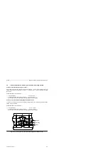
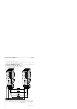
Figure 5-19.
Front View of the Digital I/O Module with a Crimp Snap-In Connector
(simplified view and not true to scale)
0.1 A
n+1
40-pin crimp
snap-in connection
L +
.0
.1
.2
.3
.4
.5
.6
.7
M
L +
.0
.1
.2
.3
.4
.5
.6
.7
M
L+
.0
.1
.2
.3
.4
.5
.6
.7
NC
NC
.0
.1
.2
.3
.4
.5
.6
.7
M
OUT
IN
n+1
n
n
1
2
3
4
5
6
7
8
9
10
11
12
13
14
15
16
17
18
19
20
1
2
3
4
5
6
7
8
9
10
11
12
13
14
15
16
17
18
19
20
a a a
a a a
a a a
a a a
b
0.5 A
EWA 4NEB 812 6210-02
5-21

