Controller
6.6 Connecting terminals and interfaces
ATE500E
System Manual, 09/2017, A5E33917696-AD
75
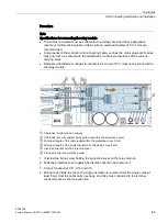
The bus can be terminated with 120 ohms via the switch S1.
Figure 6-7
Switch S1
You will find information about manufacturer-specific CANopen objects at Industry Online
Support on the Internet
http://support.automation.siemens.com/WW/view/en/50247080/133300
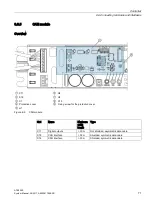
In addition to the CAN interface, there are also two relays on the CAN module. They can
switch a maximum of 30 V and 0.5 A. The pin assignments are:
Table 6- 12 Connector X11
Pin assignment
Pin
Assignment
Description
1, 2
NO contact.
CLOSED position
reached.
The relay switches on when the controller
has detected the CLOSED position and the
incremental sensor ceases to output pulses.
LED H1 is on.
3, 4 NO contact. OPEN
position reached.
The relay switches on when the distance of
the door from the OPEN position falls below
2 cm. LED H2 is on.
Note
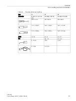
A folding ferrite (RFC-6 Kitagawa) must be attached to the beginning and end of the CAN
cable (outside the housing).


